
When I first wrote this, a long time ago - on an Apple II, as it happens - PSpice didn't exist, and surface-mount components were unusual. Times change. Equations don't.
1: Energy, Phase and Impedance
The word 'engineer' means 'inventor'. An engineer's job is to imagine something completely new, design it, build it, and make it work ... and then (often) redesign it so that it can be mass-produced for a price that customers are willing to pay. Electronic design is the process of choosing which components to connect in what sequence to make this happen.

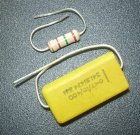
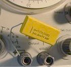
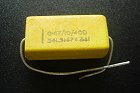
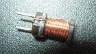
Virtually all printed-circuit boards carry a mixture of resistors, capacitors, and integrated circuits. This is an old prototype board from a system I worked on years ago, and I've included it simply to show the components. Part of the re-design process would be to lay out the board again using surface-mount components, but these are tiny and are designed to be handled by machines rather than by human fingers. The components got smaller, but my fingers didn't.
This first section is mainly about the basics. It covers the differences between resistors and capacitors, phase shift, the meaning of impedance, the value of the (jω) term, and so on. But first, I should explain what RC networks are for.
Why design an RC network?
There are two main reasons. First, it's sometimes necessary to make a circuit match the real world in a particular way. For example, a telephone has to work efficiently with a telephone line. This is achieved by arranging that the impedance of the telephone meets certain specifications set out by the phone company whose lines it will be connected to. And second, it's quite often essential to design a circuit so that it emphasizes some parts of the signal passing through it and minimises others. The obvious example is in reproducing music. Most broadcast and recorded music (in whatever medium) add pre-emphasis, which increases the apparent loudness of higher frequencies. This is done to increase the signal-to-noise ratio at frequencies where noise is at its most objectionable. The system reproducing the music must then include de-emphasis, reducing the level of these frequencies back to what it should be.
Shaping the impedance or the frequency response of a circuit is commonly done by including resistors and capacitors of just the right values arranged in just the right ways. That's what these articles are about.
Energy in resistors
Resistors are components that possess the property of resistance. But what is resistance? How do we recognise it when we see it?
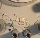

Suppose I connect a 150Ω resistor across a 1 kHz signal source and use a scope to see what's going on in the circuit. The voltage can be monitored with an ordinary probe, but examining the current waveform requires a special (and expensive) current probe. Voltage and current have the waveforms illustrated here. Trust me, or better still, check it for yourself.
I notice that the circuit current (i) is at all times proportional to the applied voltage (v). The voltage and current reach their maximum values at the same instant and go through zero at the same instant. The voltage and current waveforms are in phase.
Well, everybody knows that, but only thanks to a German schoolmaster named Georg Ohm who got interested in electicity in the 1820s, long before it was any use to anyone. He observed that when a wire was connected to a battery, the current flowing was smaller when the wire was longer. After much experiment he was able to show that voltage and current were always proportional for a given wire size, and deduced that the wire had the property of resistance which made this happen. He proudly published his findings, and the world ignored him. It was forty years later - long after he was dead - that the Ohm (Ω) was adopted as the unit of resistance.
In this case, for the 150Ω resistor, ( v / i ) = 150Ω. Always, under any circumstances. For a given voltage, the value of resistance defines the current that will flow through it.
And it follows that the value of resistance also defines the amount of power being drawn from the source. Power is the product of voltage and current [Watts = Volts x Amps] and since the voltage and current are always either both positive or both negative (or zero), their product - the power the resistor is dissipating - is always positive (or zero), because
( -v ) * ( -i ) = + ( v * i ).
So the resistor is absorbing power from the source all the time. Resistors absorb energy and dissipate it as heat.
I should probably add a word about units. Energy and power are not quite the same thing. Energy [in joules] is useful stuff, and you have to buy it. A brand-new high-performance AAA battery holds about 300 joules. Power [in watts] is the rate at which the energy is being used up, probably by being converted into heat. A watt is a joule per second. The more joules per second, the hotter the resistor will get. In fact, a good working definition of a resistor is something that absorbs energy.
Energy in capacitors
Now suppose we replace the ideal resistor by an ideal capacitor. (Here, "ideal" means that the object I think of as a capacitor actually possesses only capacitance - it has no resistance, and no inductance. This is more than just philosophical nit-picking, as I will show later on.).
The signal source is delivering the same voltage as before, so the voltage waveform is unchanged. The current waveform also remains the same shape, but it is displaced in time from the voltage waveform. The waveforms are not in phase.

Current is now zero when voltage is maximum, and vice versa. But, of course, it has to be. The current flowing at any instant is a measure of how much charge is moving at that instant. The capacitor is being alternately charged and discharged by the source. When the capacitor is fully charged - which happens when the voltage is maximum - no more current can flow. And when the source voltage has fallen to zero, the capacitor is discharging back into the source as fast as it can, and so the current is a maximum.
It follows that power - the product of voltage and current - cannot be the same for the capacitor as it was for the resistor. Both v and i are (in this case) 1 kHz sinewaves, but instead of being wholly positive the (v * i) waveform for the capacitor is alternatively positive and negative. The capacitor spends half the time absorbing energy from the source, and the other half giving it back again. It keeps none for itself. In other words, a capacitor does not dissipate any energy. A capacitor just stores energy for a while. This is the key difference between resistors and capacitors.
It doesn't really matter whether you think that the capacitor can't dissipate energy because of the 90° phase difference between its voltage and current, or that the phase difference must be there because the capacitor has no means of dissipating energy. The point is that the one always implies the other. Resistors dissipate energy. Capacitors don't.
Phase shift
The waveforms show that the phase difference between the voltage and current for the capacitor is a quarter of a cycle, or (π/2) radians, or in everyday language, 90 degrees. Now if I were to replace the capacitor by an ideal inductor (assuming I could find one) the textbooks are confident that I should then see the current waveform displaced 90° the other way from the voltage waveform. That is, instead of the current being at its most positive 90° before the voltage gets there, the current in an inductor is then at its most negative. The most positive current value is reached 90° after the maximum positive value of the voltage. Inductors behave rather like capacitors, but with phase shifted in the opposite direction.
Some people remember this by using the mnemonic CIVIL, which they interpret as meaning that in a capacitor (C), the current (I) "leads" the voltage (V), and vice versa in an inductor (L). To say that I "leads" V means simply that the I waveform is displaced to the left of the V waveform, as illustrated above. But I've always found the concepts of "lead" and "lag" a little mystifying. Are we to suppose that, because the peak current in a capacitor happens a quarter of a cycle before the peak voltage, the capacitor somehow knows that the voltage peak is on its way? Can capacitors foretell the future? This way madness lies. I shall avoid the use of the terms "lead" and "lag" and say simply that the voltage across a capacitor is phase-shifted relative to its current by -90°.
If you want a formal proof that this really is so, look in the textbooks: the current flowing in a capacitor actually depends on the rate-of-change of the voltage across it. The concepts of "lead" and "lag" arise from the convention that networks are analysed by considering what they do to sinusoidal signals. One could speculate about what might have happened if people had got used to thinking of square waves as being natural and obvious, with sinewaves derived from them by mathematical trickery, rather than the other way round. Maybe the personal computer would have been invented before the hi-fi amplifier.
By the way, I'm not going to discuss inductors much more. Their phase-shift behaviour may suggest that they could be used to make shaping networks, but in practice they're not. Why not? Because compared to capacitors they're expensive, bulky, imprecise, lossy, and expensive. OK, I'm exaggerating a bit. Inductors have their uses. But they are not the ideal choice in the networks I want to describe. I'll cover their basic behaviour and then pretend they don't exist.
Impedance
We can get back onto more solid ground by thinking again about the idea of resistance. Thanks to Dr Ohm, we know that resistance is the ratio of the voltage across a resistor to the current flowing through it. It is a property just of the resistor. It doesn't depend on the circuit in which the component is used, nor on the way the voltage is changing. So if we have a resistor of, say, 150 ohms, it will continue to possess 150 ohms of resistance no matter how much voltage is appled to it (though of course, if you keep on steadily turning the voltage up higher and higher, the resistor will eventually vanish in a puff of smoke and all bets are off). The resistance is independent of voltage, and independent of frequency. It is just as much 150 ohms at 10 Hz as at 10 kHz.
Capacitors don't behave like this. Suppose we double the frequency of the signal applied to the capacitor, from 1 kHz to 2 kHz. The scope now shows that the current waveform is twice as big as it was before, though the voltage waveform remains the same. Trying it at 500 Hz, we find that here the current is halved. It seems that the ratio of voltage to current in a capacitor depends inversely on frequency.
Why does this happen? How can the current depend on frequency? The answer is to do with what current actually is. Current isn't a thing in itself, it's the label for a process. When we say "current is flowing" we really mean charge is moving. More precisely, in a capacitor, the current flowing (in amps) is the rate-of-change of the charge (in coulombs) it happens to be holding. So if the frequency increases, the charge moves faster, and we see the current increase.
When I try the experiment again with several capacitors of different value, I find that the bigger the capacitor, the bigger the current. So the voltage-to-current ratio for a capacitor is inversely proportional to both frequency and capacitance.
It is very handy to be able to define a component in terms of the ratio of its voltage to its current. But we clearly ought not to speak of the "resistance" of a capacitor. Resistance implies that voltage and current are in phase, and that power is dissipated. A different word is needed to express the idea of the voltage-to-current ratio in a more general way, one which does not carry the implication that the two have to be in phase. This word, of course, is impedance, written Z, and measured in ohms.
But what is it? Like resistance, impedance limits current. If I apply 1v at 1 kHz to a capacitor and see 1 mA flowing, I know that the component has an impedance of 1 kΩ (at 1 kHz, anyway). The capacitor is somehow limiting the current, just as a resistor would. How does it do that?
Look back at the voltage and current waveforms for the capacitor. Since impedance is ( voltage / current ), could we maybe divide the voltage waveform by the current waveform and get at the impedance that way? Well, no. For one thing, the current keeps passing through zero, and dividing anything by zero gives 'infinity' as the answer. The voltage regularly passes through zero too, so all we can conclude is that their ratio is jumping rapidly between zero and infinity. That isn't much help.
So impedance is apparently not something that can be defined at a particular instant, as voltage can. It must be a property of the component that only makes sense when it's averaged over some sensible period of time, such as a full cycle of the applied voltage sinewave. This is believable, because the current flowing in or out of the capacitor at any instant depends not only on the applied voltage but also on how much charge the capacitor happens to have stored at that instant. This charge movement averages out over a complete sinewave cycle. And the impedance of a capacitor depends very much on the frequency at which it is measured.
I can now write that, for a capacitor,
ZC = ( v / i ) , and ZC is proportional to (1 / Capacitance ) * (1 / Frequency )
If I could get hold of a few ideal inductors (ha! in my dreams!) and do the experiment with them, I should likewise be able to conclude that for an inductor
ZL = ( v / i ) , and ZL is proportional to ( Inductance ) * ( Frequency )
Inductance is measured in Henrys and capacitance in fractions of a Farad, though if Faraday's name had to be abbreviated in that insulting fashion, why didn't they go all the way and call the unit a Far? Or why not measure inductance in Hens? (Then we could go on to define 1 Hen = 1000 Chicks, and 1 Chick = 1000 Eggs ...)
It would be nice if we could write that
Impedance [Ω] = ( v / i ) = 1 / ( Capacitance [F] * Frequency [Hz] )
but we can't. The definitions of the units won't allow it. It turns out that the angular frequency ω (in radians per second) must be used instead of the common-or-garden frequency f (in Hz). Irritating, but life is like that. From here on in, unless I specify otherwise, frequency means angular frequency, written "ω" and pronounced "omega". Angular frequency (ω) is related to "ordinary" frequency (f) like this:

ω = 2 * π * f ...where π = 3.141592554... unless of course it's a pork π, like this one.
Since the impedance of capacitors and inductors (or, for purists, the reactance of ideal capacitors and inductors) depends on frequency, it follows that the impedance of a network containing these components also depends on frequency. It is meaningless to talk about the impedance of a network built from resistors and capacitors (that is, an RC network) without at the same time specifying the frequency. Actually, that's the point of RC networks. If we wanted an impedance that was independent of frequency, a resistor would do.
Phase shift of an impedance
So impedance (in Ω) is just ( volts / amps ). Fine. Suppose that we happen to have, lying around, an ideal 470 nF capacitor and an ideal 54 mH inductor. We're in the realms of fantasy now, you understand, where the theorists' little feet are floating some inches above the ground we lesser mortals walk on. We (or anyway, they) could find the impedance of each component at 1 kHz by putting each one in turn across the generator terminals and measuring the voltages and currents.
The experiment is complicated by the phase shifts each component introduces, so to keep it simple let's measure the voltages and currents in RMS terms. RMS (root-mean-square) is a way of expressing an AC voltage in terms of its DC equivalent. It involves integration, and it's in the textbooks if you really want to know, but for now it's enough to accept that it's what you would read off an AC voltmeter or ammeter in the circuit.

It turns out that with 1v (RMS) applied, each component draws just under 3 mA (RMS). This means that at 1 kHz each has an impedance of
( v / i ) = 1v / 2.9 mA = 339 ohms.
A capacitor is a very different type of component from an inductor, yet 470nF and 54mH both have the same impedance (at 1 kHz). Something is obviously missing in the definition of impedance if it does not allow us to see at once that the two are different animals, and the missing information must be to do with phase shift.
For a capacitor C,
Impedance = ( v / i ) = ( 1 / ωC ) * (something)
where the (something) has to specify that v and i are 90° apart. In fact, it must show that v is at -90 degrees to i.
Similarly, for an inductor L,
Impedance = ( v / i ) = ( ωL ) * (something else)
where the (something else) has to specify that v is at +90° to i.
But both the (something) and the (something else) must not affect the actual size of the impedance, since that depends only on the ratio ( v / i ).
The problem is got round by inventing a special symbol, j, which is used like this:
Capacitor's impedance = ZC = (1/ωC) * (1/j)
Inductor's impedance = ZL = (ωL) * j
The (1/j) term is a warning label, indicating that the impedance is not a pure resistance - that is, that v and i are not in phase. Instead, the voltage has a phase shift of -90° from its current. Similarly, j means that the voltage is phase shifted +90° with respect to its current. The (j) terms simply indicate that there is a phase shift, and whether it is positive or negative.
But what is (j)? What does it mean? If we multiply the two (j) terms together, the (j)s vanish:
(j) * (1/ j ) = 1
No (j) there, so no phase shift. We can interpret this as two 90° phase shifts acting in opposite directions and thus cancelling each other out.
Taking now the ratio instead of the product,
(j) / (1/j ) = ( j * j ) = ( j2 ) = ( ? )
The presence of (j * j) must mean that the two 90° phase shifts act in the same direction, adding together to give 180° total phase shift. But shifting the phase of a sinewave by 180° is the same thing as turning it upside down - that is, inverting it, so that the maximum positive peak appears in the position where the maximum negative peak used to be, and vice versa. And an inverting amplifier has a gain of (-1). So the (?) - that is, (j2) - must be (-1), and so (j) must be the square root of (-1), whatever that might mean. Negative numbers can't have square roots, can they? It seems to be a weird Zen concept, like the sound of one hand clapping. But it is immensely useful, because j can be manipulated in the equations like any other variable.
Returning now to the definitions of impedance, we have
ZC = 1 / jωC, and ZL = jωL
The original choice of using the j label to mean "this impedance has a +90° phase shift" and (1/j) to mean "this impedance has a -90° phase shift" makes j and ω always occur together, like cornflakes and milk. Frequency is always associated with phase shift, so it's helpful to write them together, like this:
ZC = 1 / (jω) C, and ZL = (jω) L
The (jω) term provides the key to unscrew at least some of the inscrutable.
Series and parallel RC networks
The simplest possible RC networks are those containing just one resistor and one capacitor. The components must be either in series or in parallel.
We know the impedance of each component, so we can quickly find the impedance of the combination. For the series case,
ZS = R + 1 / (jω)C = [ 1 + (jω)CR ] / (jω)C
and for the parallel case,
ZP = R (1/jωC) / [ R + (1/jωC) ] = R / [ 1 + (jω)CR ]
The term [1 + (jω)CR] appears in both. Now, impedance has the dimension of ohms, just like resistance, and R is measured in ohms, so [1 + (jω)CR] must be a dimensionless number. And since the first part [the 1] is obviously just a number; the second part [the (jω)CR] must be a number, too. But as (j) is a dimensionless number - albeit a rather peculiar one - and (ω) is a frequency, then (CR) must have the dimension of (1 / frequency). Or to put it the other way round, (1/CR) is a frequency.
The equations are saying that these two components, C and R, define between them a single unique frequency that depends on their values and on nothing else. It is characteristic of this network, and so to distinguish it from all other values of ω it is given the special label of ω0.
ω0 = ( 1 / CR )
The impedances can now be rewritten as
Series: ZS = [ 1 + (jω)CR ] / (jω)C = R [ 1 + (jω/ω0) ] / (jω/ω0)
Parallel: ZP = R / [ 1 + (jω)CR ] = R / [1 + (jω/ω0)]
These equations look pretty simple. There are only two variables: R and (jω/ω0). The equations are saying that the impedance of each network is R (which is constant, of course), modified by the frequency-dependent term (jω/ω0). And since ω is the frequency of the signal we apply to the network, (jω/ω0) is this signal frequency expressed as a fraction of the network's characteristic frequency ω0.
In other words, R and C in combination behave like a resistor whose value varies with frequency. Well, of course they do.
Impedance as a vector
Something important obviously happens to Z when ω = ωo, because at this frequency (jω/ωo) becomes just (j), and we can write
Series: ZS = R (1 + j) / j
Parallel: ZP = R / (1 + j)
But what does (1 + j) actually mean? How do you add the square root of (-1) to something? And if you did, what would it look like?
The key to understanding the next bit is to remember that j was only invented so that we could tell the difference between a positive phase shift and a negative one. Multiplying by j means, there is a +90 degree phase shift. Now, we cannot just add something with a 90° phase shift to something else with zero phase shift. Thiat would be adding apples to oranges. But we can use geometry to see what the combination might mean. Representing the 90° phase shift as the 90° rotation of a vector makes it easier to see what's going on.
Mathematicians call terms involving j "imaginary numbers", as well they might, to distinguish them from "real" numbers, like 150 ohms. The mathematicians even helpfully label imaginary numbers with an "i", to show that they are imaginary. But as engineers already use "i" to mean current, that won't do, and so "j" was adopted instead.
Numbers such as ZS, that are partly real and partly imaginary, are known as "complex" numbers.
 To sketch a complex number, we need to imagine a plane in which the real and the imaginary can coexist. This is at first a really difficult idea, because it doesn't seem to tie in to anything that can actually be measured on the lab bench. It turns out, though, to show exactly what can be measured.
The "complex plane", so-called, looks like this set of axes on the left. On it we can sketch complex numbers, which are written as:
{Real part} + j * {Imaginary part}
which can be interpreted as
{Stuff to do with the RMS ratio of volts to amps} + {Stuff to do with the phase angle between volts and amps}.
Take for example the series network. We have:
Series: ZS = R * (1 + j) / j = {R} + {(1/j) R}
This is almost - but not quite - in the form we want. The j should be on top. To get it there, all we have to do is multiply both terms by (j/j) (which is 1, of course, and multiplying by 1 won't change anything) and now
Series: ZS = {R (j/j)} + {(j/j2) R} = {R} - {j R} . . . . . . . . . . . because j2 = -1.

The expression has two terms, one involving j and one not. The {-jR} term has by definition a -90° phase shift relative to the {R} term. They point in different directions. So each term must be represented as a vector - that is, a quantity having direction as well as size.
The sum of the two terms is evidently their vector sum. It is possible to add something with 90° phase shift to something else with no phase shift and get a meaningful answer. Unfortunately, the answer is itself a vector. It too has a phase shift, as well as a magnitude. We need to know both these quantities in order to make use of it. They are quite easy to find, though.
Simple geometry tells us that the magnitude (or modulus) is . . . . . . . . . |ZS| = √[ Real2 + Imaginary2]
and the phase angle (between the vector sum and the real axis) is . . . . . Φ = arctan [ Imaginary / Real ]
Doing the calculations for ZS (which is [ R - j R ] when ω=ω0),
|ZS| = √[ R2 + (-R)2] = √[ 2 R2] = 1.414 * R
Φ = arctan [-R / R] = arctan [-1] = -45 degrees.
In other words, at the magic frequency of ω=ω0 the impedances of the resistor and the capacitor are equal, and the capacitor's phase shift of 90° is counterbalanced by the resistor's phase shift of 0, so that the combination sits half-way, at 45°. At other frequencies, the magnitude and phase of ZS will evidently be different.
So using the complex plane demonstrates that impedance has two aspects: magnitude and phase. Both can be measured. Magnitude means size - it is the (voltage/current) ratio for the network. We are dealing with AC signals, so the values of voltage and current in the ratio must be RMS values. If we put 1v RMS across the network and find that this causes a current of 2.9 mA RMS to flow, we can say that the magnitude of the impedance is 339Ω. But the magnitude of the RMS (voltage/current) ratio tells us nothing about the phase relationship between the actual voltage and current. This is a separate piece of information. We could only find it by using a phasemeter or (less accurately) a scope to measure it. Phase is just as important as magnitude. In fact, the two are inseparable - like a full-face and profile photograph, each tells only half the story.
I chose ZS as the example to illustrate how to get at the magnitude and phase of an impedance because it could be stated simply as a vector sum. ZP has the (1+j) term in the denominator, and looks more difficult to sketch. To get round this minor obstacle, I must rearrange the expression slightly. Here, the trick is to remember the identity
(1 + x) * (1 - x) = (1 - x2)
because if I replace x with j:
(1 + j) * (1 - j) = (1 - j2) = (1 - (-1)) = 2.
To get rid of the awkward denominator term, I need to multiply by (1 - j) / (1 - j) - that is, by 1 - to get
Parallel: ZP = R / (1 + j) = R (1 - j) / [(1 + j)(1 - j)] = R (1 - j) / [1 - j2]
= R (1 - j) / [1 + 1] = (R/2) - j (R/2)
so |Zp| = √[(R/2)2 + (-R/2)2] = √[(R2) / 2] = R / 1.414
Φ = arctan [(-R/2) / (R/2)] = arctan [-1] = -45 degrees.
So at ω=ω0, the phase angles of Zs and Zp are both -45°, and the magnitude of ZP is exactly half that of ZS. But as I now know that the impedances of R and C are equal at ω=ω0, this is not a surprise.
In the next chapter I explain how you can quickly sketch the frequency response of these networks.
... Part 2: Z-ω curves ...