
")
Telephones looked like this when I was young. Not just the one in my parents' house - all telephones looked like this. Even the Prime Minister's. They were all identical, black and shiny, and very heavy. The handset alone weighed 1lb. Today's little mobile phones weigh 80 grams - barely a fifth of a pound.
This was the first telephone to include a bell, which rang loudly whenever someone was calling. It was reminiscent of the bells used in the great houses to summon a servant, and I suspect this influenced the attitudes of its users. A ringing telephone had to be answered at once, even if this meant interrupting a conversation with a real person present in the room.
The telephone was heavy because it was made of quarter-inch-thick Bakelite and full of metal. The bell, the line-matching transformer, the dial, the cover plate - even the capacitors had metal cases.
 This telephone was designed to stay in one place, usually a desk or the cold and draughty hall of the subscriber's house. Calls tended to be kept short.
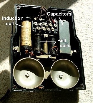
With the cover plate removed the scale of the engineering is clear. It was built solidly to last a long time. It did, too.

'Candlestick' telephones were designed to ensure that the microphone stayed more or less vertical all the time. It didn't work well if it was tilted too far (though it did benefit from a good shaking every now and then).
But in the 1920s a more user-friendly microphone was developed and handsets became possible. The 'microtelephone' was introduced in 1929, and for the first time a telephone user had a hand free to make notes on the conversation or simply scratch his nose.
The bell-set was still housed in a separate box on the wall, so the obvious next step was to include it within the telephone case. The result was the Telephone No. 332, which came into general use around the end of the 1930s. It was still being manufactured thirty years later.
Circuit Diagram
The complete circuit diagram of the Telephone No. 332 shows how remarkably few components were needed.
There's a microphone, receiver and bell, a dial, a transformer (the "induction coil"), a couple of resistors (wound non-inductively on the transformer core), a hookswitch, two capacitors, and that's it.
In fact, this telephone represents a most ingenious design in which practically every component does two or more separate jobs. Components cost more in those days.
To work properly, a telephone must meet several separate criteria:
- Alert the user when an incoming call arrives;
- Transmit routing information to the exchange when an outgoing call is to be made;
- Draw the correct current to signal to the exchange that the telephone is in use;
- Transfer speech power optimally to and from the line by matching the (nominal) line impedance.
The diagrams below illustrate how each of these criteria is met. For simplicity I have deliberately not shown those parts of the circuit that are disconnected, and closed switches are drawn as short-circuits.
Ringer
The ringer circuit is straightforward. When the telephone is on-hook - that is, when the handset is in its cradle - the hookswitch contacts are open, and only the bell is connected across the line. The 2μF capacitor blocks dc, which would prevent the bell from working properly and more importantly would signal that the telephone is off-hook.
The bell needs a decent current to work. An exchange would apply typically 75v (rms) at 17 Hz to the line, which is quite enough to make you jump if you happen to be touching the wires when an incoming call arrives. This simple truth has surprised many young technicians and engineers. The older ones had learned long ago why their tools had insulated handles.
Dialling
The rotary dial transmits the destination of an outgoing call to the exchange as a sequence of pulses by repeatedly making and breaking the line.
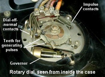
A dial is a complex mechanism based on a toothed wheel. When the user rotates the wheel (by rotating the dial with a finger) this action compresses a spring. When the dial is released, the spring drives the wheel back to its rest position at a constant speed (set by a governor) and each tooth on the wheel briefly opens the dial impulse contacts as it moves past them, generating a pulse train. The further the dial is rotated, the more teeth pass the impulse contacts, and the more pulses are generated.
The series RC network connected across the impulse contacts modifies the pulse shape, prevents arcing at the contacts and also mutes the bell. It makes use of the bell's dc blocking capacitor.
 The dial is supposed to deliver 10 pulses per second (but the exchange equipment was wisely designed to accept anything between 7 and 12 pulses/sec) at a make/break ratio of 1:2. Dialling a "4", for example, would interrupt the line current four times.
The actual value of line current flowing would depend on the length of the line back to the exchange and the state of the exchange battery. It could have been anything from 35 to 140 mA.
Holding loop
When the user picks up the handset, current begins to flow in the line. The 'A' relay at the exchange operates when line current is detected. (In fact, this relay is also used to monitor the breaks in line current during dialling.) When the call ended. this relay was released.
It was essential that line current flowed also through the microphone. The microphones used at the time converted varying sound pressure to varying resistance. A small box of carbon granules (essentially, soot) had a diaphragm as one face of the box. When the user spoke, the sound pressure on the diaphragm varied, compressing the carbon granules, changing their resistance, and so causing the instantaneous line current to vary in sympathy with the caller's voice.
The resistance of a carbon microphone is typically 40Ω, so with a line resistance of up to 1,000Ω the holding loop current would have been 35 to 100mA. Modern exchanges limit the current a telephone can draw to much less than 100mA.
Speech circuit
Now for the clever bit. The speech circuit has to do several things at once:
- Move all the signal power generated in the microphone out to the line;
- Move all the signal power delivered by the line into the receiver;
- Prevent any power being generated by the microphone from reaching the receiver;
- and unfortunately, these objectives conflict. They can't all be met simultaneously.
So the designers had to choose, and they decided that it was most important to preventing the user from hearing sounds entering the microphone. Hearing yourself speak - "sidetone", as it's called - makes you talk more quietly, which is bad news for the person you're talking to.
Arranging a circuit so that zero energy reaches just one component involves balancing a bridge, like this Wheatsone bridge on the left: no voltage appears across the detector D when the impedances in the arms have the same ratio. Unfortunately, one key impedance in the telephone speech circuit is the line impedance ZL, and this depends on how long the line is.
 A local-loop pair may pass through many different types and sizes of cable on its way from the exchange to the telephone, and whilst it's generally assumed that ZL = 600Ω, in practice it's quite different. BT currently recommend that telephone designers assume the line can be modelled by this simple network. (I discuss this RC network and many others in more detail here.)
Given the need for a balanced bridge, it was impossible to achieve both high sending efficiency and high receiving efficiency, so the designers settled for the least-worst option - they degraded both, equally, as I will explain below.
There were a couple of minor issues with the transducers themselves. The microphone had to be fitted with an RF bypass capacitor, since its carbon granules could act as a rectifier - strong local radio signals might be picked up and played to the users. Also, the receiver was based on an electro-magnetic transducer, and needed a dc blocking capacitor. Once again, the bell capacitor was used.
Anti-sidetone induction coil (ASTIC) circuit
It's easier to see how the speech circuit works if it's re-arranged slightly. The 800-turn winding and the components in the blue box are in series, so they can be swapped over without altering the circuit's essential structure ...
... and now it can be re-drawn like this.
R1 is the balance impedance, ZL is the line impedance, the 2μF capacitor blocks dc from the receiver, and R2 is just a nuisance. It absorbs a small amount of receive power, but it doesn't affect the circuit's operation. Similarly, the capacitor is too large to make much difference at speech frequencies.
In order to explain how this clever circuit works, I'm going to ignore these unimportant components too.
Telephone transmitting and receiving
Transmitting: The microphone generates a varying current in the line, and in its transformer winding. This in turn makes current flow through the balance's winding, and through the balance impedance. The receiver's transformer winding is arranged to generate the same voltage as that appearing across the balance, but in the opposite direction, so that no current flows in the receiver.
Receiving: The line delivers a varying current which necessarily flows through the microphone and its transformer winding. This in turn makes current flow through the receiver's winding, and through the receiver. But the voltages appearing across the receiver's winding and across the receiver are arranged to be equal and opposite, so the net voltage across the balance is zero, and no current can flow through it.
I've explained transmitting and receiving separately, but of course the telephone can handle both at the same time. The speech circuit is linear, which means that the current flowing in (say) the microphone when the telephone is receiving simply adds to the current caused by the user speaking. The two currents don't interfere with each other. Each behaves as though the other wasn't there.
To make best use of the available speech power, the telephone's impedance must be matched to the line's. The transducers' impedances are fixed, of course, so impedance matching was achieved by choosing the correct turns ratios in the transformer.
Incidentally, there's a simple reason why the telephone was designed as it was, and not as shown in the diagram above. It allowed the handset cord to be 3-wire instead of 4-wire. When you're designing for mass production, these details are important.