
This page gives a brief explanation of what valves are, how they work, and how they are (or were) used.
It's mainly here to entertain my friend Don.
What is a valve?

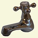
The first television set I ever saw appeared in our house in about 1950. It looked like this - except it was in a box, obviously. My dad had built it from a kit. They made their own entertainment in those days.
There was only one channel - BBC - broadcasting on 45 MHz. The programmes were rubbish, the picture was a grainy black and white on a 9" tube, and yet my brother and I were entranced. It was the most amazing thing we had ever seen. Moving pictures! Right there in our living room!
Valves made TV possible.
Manufactured in large numbers during the war, valves were suddenly cheap and widely available. TV receivers became affordable for the first time.
Some pedants refer to valves as 'thermionic' valves, to distinguish them from the valves plumbers fit, whilst Americans know them as 'vacuum tubes'. They look like oddly shaped light bulbs, or fat metal tubes. There are six of them visible in the picture. (OK, Don, seven if you count the CRT).
How does a valve work?
Think of a plumber's water valve, or a tap. It's basically a pipe with an adjustable vane inside it. The vane can be rotated from outside the pipe between fully closed and fully open. You can control precisely how much water flows through the valve by adjusting the angle of the vane.

A valve like those in the TV set works by controlling the flow of electric current. The key point is that both types of valve allow an external force to influence what's happening inside.
That's enough about water. From now on, valve means the kind you would find in an old television like the View Master.
These valves control electric current. A current is a stream of electrons, all flowing in the same direction. So a valve needs a source of electrons, a target for them to aim at, and a force to move them. Plus, of course, a means of controlling how many electrons are moving.
The simplest possible way to achieve this is by means of a structure consisting of just three components. The structure is known as a triode.


Engineers needed a way of thinking about a valve without worrying about unnecessary details such as its physical size or the actual shape of its components. They came up with a descriptive symbol. I found this version in the March 1923 edition of Modern Wireless, and it's still recognisably a triode.
At the bottom of the diagram is the filament. Its job is to emit electrons. At the top is the anode (or plate, as Americans say). It is connected to a large positive voltage, so the electrons swarm towards it. Between the filament and the anode is the grid. It is not solid - the electrons can pass right though it.
But when a negative voltage is applied to the grid (that is, when the grid is made more negative than the filament) some electrons become discouraged on their journey, and turn back. A sufficiently large negative voltage stops all the electrons from passing whilst a zero voltage allows them all to pass unhindered. Allowing the grid to become more positive than the cathode is generally considered a bad thing to do.
It's essential that the electrons can move freely, so the whole structure operates in a vacuum, held usually inside a glass bottle. The base carries pins which plug into a valve-holder, allowing the valve to be replaced when it fails. And it will fail, just as a lightbulb will fail. Valves are not reliable components.
How is a valve used?

A valve is an amplifier. Its output signal is much bigger than its input signal. So in principle a simple radio receiver could be made from a single valve with an aerial connected to its input and a set of headphones at its output. Modern Wireless (July 1923) shows how. The tuned circuit (L1, C1) selects the frequency. L2 provides positive feedback - they called it "reaction" then - which increases gain and selectivity right up to the point when the circuit begins to oscillate and becomes a transmitter.
In the accompanying list of Materials and Components Required, it says simply "1 valve". There is no further clue as to what type of valve is needed here, so I assume there was only one type of valve available. The world had not yet realised what a fantastic transformation these and their successor devices (transistors and integrated circuits) would bring within a couple of generations. In the 1920s, valves existed mainly so that serious experimenters could build radio receivers.
Thirty years later the serious experimenter could build his own television set. The circuit below is the video receiver for the View Master TV shown at the top of the page. It consists of three RF amplifier stages, a detector (V4) and an output valve driving the CRT.
Triodes have one grid, but these newer amplifier valves possess three (and are therefore called pentodes). The additional grids are known as the 'screen' and the 'suppressor', and including them greatly improves the valve's performance. I'll explain why, later.
Another obvious difference is that the filament is no longer the source of the electron stream. Instead, the filament now heats an electrode known as the 'cathode', which is specifically designed to emit copious quantities of electrons in a smooth stream.
The RF valves (the fat metal tubes in the photograph above) were EF50s.
A huge number of these were manufactured during the war for use in radar receivers.

What's inside a real valve?
The best way to find out is to have a look. I put an ECC83 dual triode in a vice and gently crunched the glass envelope until it fell away, then after removing various layers of mica I was left with the important bits. The left-hand photograph clearly shows the structure: a small tube (the cathode) surrounded by a spiral of wire (the grid) inside a large rectangular metal box (the anode). The tiny heating filaments can be seen in the picture on the right, which also shows how the structure is supported and connected to the outside world.
Each anode is 12mm wide - or, more probably, half an inch.
The pins (on the base) are 1mm in diameter.


How does a valve behave?
Valve manufacturers helpfully publish the characteristic curves of their products.

These graphs are produced by putting a fixed voltage between the grid and cathode of a triode, and gradually increasing the anode voltage whilst measuring the anode current.
When the grid voltage is zero, the graph is almost a straight line, reaching 5mA anode current at about 225v. In other words, the valve is behaving much like a 45kΩ resistor (whist quietly dissipating just over a watt at its anode, plus nearly another 2 watts in its heater - valves get warm!)
Making the grid more negative reduces the anode current, as you would expect, and anode current falls to zero when the grid voltage reaches around -5v .
So a relatively small variation in grid voltage can produce quite a large variation in anode current. This means the valve can amplify signals.
The next obvious question is, by how much?
How do you make a valve amplify?
Here, the red line indicates how the anode current and voltage will move as the grid swings up and down by 0.5v.


An amplifier makes a signal larger. The extra energy comes from the power supply.
A valve needs a large positive supply voltage. In this example I've chosen +250v, which is well within the valve's capabilities, and high enough to hurt you if you accidentally touch it. The supply voltage is often known as 'HT+', or (by Americans) as 'B+'.
The valve amplifies by using the varying grid voltage to cause a varying anode current. But the amplifier output needs to be a varying voltage, perhaps to feed the next amplifier, so a resistor is required to convert the current into a voltage. How big should it be?
I've chosen 51kΩ here, simply to explain what's happening. When anode current is zero, the full 250v appears across the valve, and if (by some miracle) the voltage between anode and cathode could be forced to be zero, the anode current would be (250v / 51k) = 4.9mA. The relationship between anode current and voltage is fixed by the 51k load. If, for example, anode current happened to be 2mA, then the anode voltage would have to be 150v.
What should the anode current be when there is no input signal? The designer must decide. In this example, I chose 1.5mA, which corresponds to a grid voltage of about -1.1v (and an anode voltage of 170v.) This coordinate (1.5mA, 170v) is known as the operating point. I could have fixed it almost anywhere in the graph (provided the grid voltage was negative, of course).
Now, suppose the input signal is a 1v peak-to-peak sinewave. It will cause the grid voltage to swing up and down by 0.5v. This in turn will cause the anode voltage to move back and forth along the 51kΩ loadline, from say 145v to 195v. The 1v p-p input signal yields a 50v p-p output signal. This amplifier has a gain of 50.
How do you set the valve's operating point?

The grid must be kept more negative than the cathode. But this just means that the cathode must be kept more positive than the grid, and it's easy to achieve this by adding a resistor S between the cathode and ground. Anode current (which is the same as cathode current) flows through S, so the cathode must be more positive than ground. Provided the grid is connected to ground, the grid must be more negative than the cathode.
However, the cathode resistor S introduces negative feedback into the circuit, which would reduce the gain. To avoid this, it's common to add a capacitor C in parallel with S. C is chosen to have an impedance that is much lower than S at the frequencies the amplifier is designed to handle.
In the example above, I wanted -1.1v on the grid at an anode current of 1.5mA. Ohm's law says that S should be 733Ω, so I'd choose 750Ω. If the circuit is an IF amplifier handling 470kHz signals, C must have an impedance of (say) 70Ω at 470kHz, so C must be about 4.7nF. If it's an audio amplifier than must work down to 25Hz, C would be a 100μF electrolytic.
The designer of the View Master video receiver (above) chose R12 =220Ω and bypassed it with C10 =500pF, which means that the stage will amplify down to (1 / 2.π.220.500E-12 ) = 1.5MHz.
What's wrong with triodes?
It is said that beam tetrodes such as the KT66 and the 807 were only developed because a well-known manufacturer held a patent on the suppressor grid.
Thanks to our daughter-in-law Ewa Hearfield (her other work is here and here) of Ewapix for this clear photograph of the 807.

A triode doesn't work well at high frequencies because the signal leaks back through its anode-grid capacitance. To reduce this, an extra grid is added between the anode and the control grid. This new electrode is known as the screen grid (or just the screen), and the resulting four-electrode valve is called a tetrode.
The screen is kept at a high positive potential, and is usually bypassed by a suitable capacitor.
In the View Master circuit above, the screen of V2 is fed by R10 = 2K2 and bypassed by C7 = 500pF, giving a lower cut-off frequency of (1 / 2.π.2200.500E-12 ) = 150kHz, well below the frequencies the valve must amplify.
Adding the extra grids dramatically improves the anode characteristics too. The anode current is now much less dependent on the anode voltage. Tetrodes and pentodes are better amplifiers than triodes.


Unfortunately, the electron beam striking the anode knocks some secondary electrons loose. When the anode is less positive than the screen (as it can easily be for part of a cycle) they move to the screen instead of back to the anode. The result is an unwanted kink in the anode current/voltage characteristic.
This new problem is solved by adding yet another grid, known as the suppressor, between screen and anode. The valve now has five electrodes, and is known as a pentode. A beam tetrode (such as the 807 sketched here) is a sort of pentode that uses fixed metal plates instead of a suppressor grid.
Triode, tetrode, pentode (and the list goes on...) It seems that engineers were happy counting in Greek in those days.
The valve as an amplifier - what's gm?
An ideal voltage amplifier delivers an output that is an exact and predictable multiple of its input voltage. The ouput should depend on the input voltage and on nothing else. A valve amplifier is far from ideal.

I find it helpful to think of an amplifying device - be it a valve, transistor, opamp or something else - as a black box. The box has an input impedance, an output impedance, and gain (sometimes in both directions).
The valve works by forcing the anode current to vary in sympathy with the grid voltage. Since (I / V) is a conductance (g), the valve is really a transconductance amplifier with a 'gain' of gm. A little circuit theory transforms this model into the more useable form of a voltage amplifier, and the term [gm rA] is often written as μ, the 'amplification factor' (that is, the voltage gain).
gm (mA/V) is a measure of how many mA the anode current changes for each 1 volt change in grid voltage, with the anode voltage kept constant.
rA (kΩ)is a measure of how much the anode voltage changes for each 1mA change in anode current, with the grid voltage kept constant.
It's clear that valve characteristics are far from linear. This explains what some musicians call the 'warmth' of a valve audio amplifier.
Engineers like me call it 'distortion'.


Ideally, gm should be very large (so that spare gain can be traded for linearity, or bandwidth), whilst rA should be very small (so that the load does not affect performance).
Both gm and rA can quickly be inferred from the valve's characteristic curves. gm is the slope of the anode-current-vs-grid-voltage curve (the transfer characteristic) whilst rA is the slope of the anode-current-vs-anode-voltage curve (the anode characteristic). Both values must be measured at the chosen operating point.
In the example above, I chose an operating point of 170v and 1.5mA, with the grid at -1.1v. By eye, gm is about 1.8 mA/v and rA is about 55 kΩ, so μ is about 100. However, I used an anode load of R= 51kΩ in the example, so only half the output swing will appear across this resistor - the other half is wasted, as it's across rA.
There's much more on valves at the National Valve Museum , and I've also written about the Wireless Set 'A'
But paradoxically, it would actually be helpful if rA could be made larger - and that's the other reason why pentodes were invented. The anode characteristics of a pentode (or a beam tetrode) are much flatter than those for a triode, as I show in an earlier graph. For these devices, a change in anode voltage results in a far smaller change in anode current. In other words, rA is higher in pentodes. An EF86 (typically, rA=2.5MΩ, gm=2.0mA/V) makes a better amplifier than an ECC83 (typically, rA=62kΩ, gm=1.6mA/V). Pentodes (like the EF50) make good RF amplifiers.
On the other hand, transistors are better still. And smaller. And lighter. And they need less power. And ... well, you get the idea.