The Wireless Set A was developed by SOE in 1942 for use by British agents operating in wartime Europe. This page gives the circuit diagrams and part values listed in the user manual . I have taken the opportunity to highlight some obvious mistakes in the circuits - the draughtsman was probably working under some pressure.
The user manual for this suitcase radio turned up in my files.
RECEIVER
The receiver consisted of an RF stage (EF39) followed by a mixer/oscillator (ECH35), an IF stage (EF39) and a detector (EBC33) driving headphones.
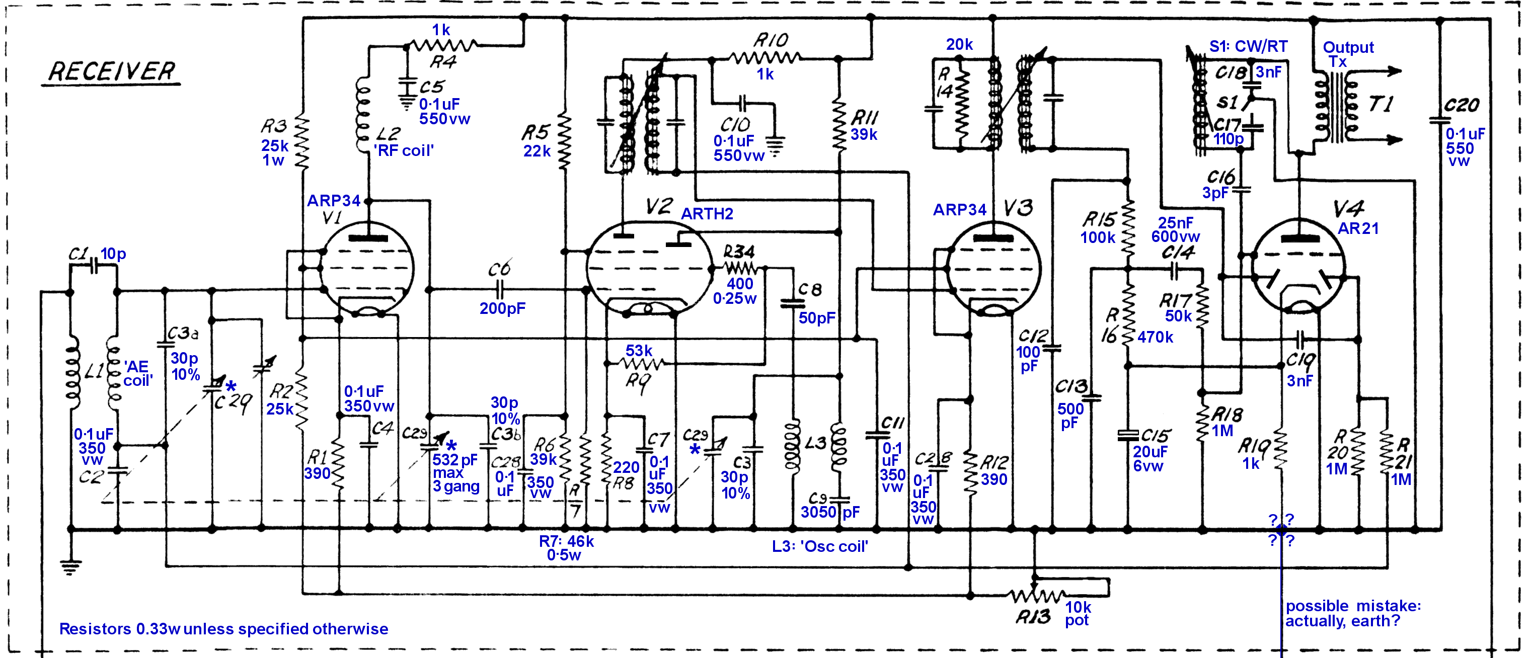
RF and oscillator tuning was by a 3-gang 500pF variable capacitor. The IF was the usual 470 kHz. The CW/RT switch S1 presumably narrowed the bandwidth when receiving morse transmissions. The pot R13 must have been the front-panel GAIN control, and it seems to do this by varying the screen-grid voltage for V1 and V3. Construction details for L1 and L3 are not given.
It seems clear that R19 should be connected to earth - the draughtsman omitted a blob.
TRANSMITTER
The transmitter was designed solely for use with the morse key. It used an 807 as a crystal-controlled oscillator running at between 3 and 4 MHz, feeding the antenna though a tuneable tank circuit. The 807 only drew cathode current when the morse key was pressed.
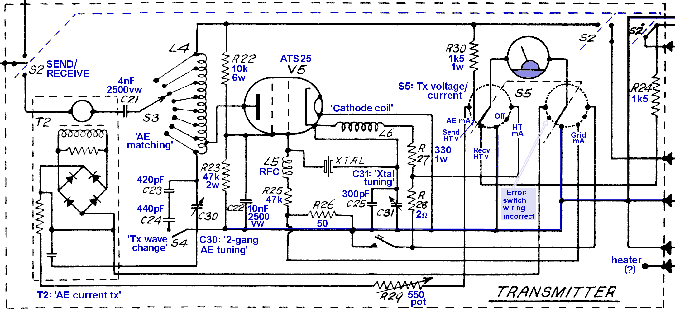
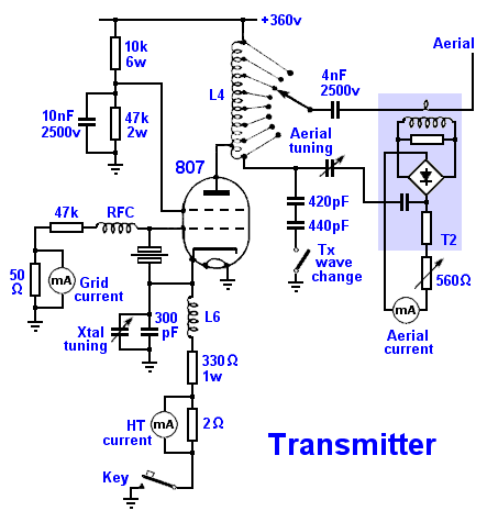
This circuit is a little difficult to follow (and I think includes mistakes around the switch S5) so I've redrawn it here. I think the short-circuit across the bridge used in measuring antenna current is probably also a mistake.
No details are given of coil construction, nor of the values of the two tuning capacitors C30 and C31.
The 'Tx wave change switch' S4 allowed the oscillator to run as a frequency doubler, giving an extended frequency range of 6 to 8 MHz.
The 550Ω pot R29 was presumably factory-set to suit the particular antenna-current measuring block (T2) installed.
The full-scale deflection of the milli-ammeter connected to S5 is not specified, but R30 is 1w, which suggests it was intended to carry around 20 mA (at 0.6w dissipation); but the voltage drop across R30 would then be only 30v, which makes no sense. If HT voltage measurement was done via a dropper resistor R30 and a 25 mA meter (say) then R30 should have been closer to 18k 7w. It's not obvious to me how HT voltage was measured. Perhaps the milliammeter had an unusually high resistance, or the values given for R24 and R30 are incorrect. It would even have been possible to use the 807 screen-grid dropper resistors to derive a current in the meter proportional to HT voltage (with the key not pressed) but the designer didn't do this. It's a mystery.
MAINS POWER PACK
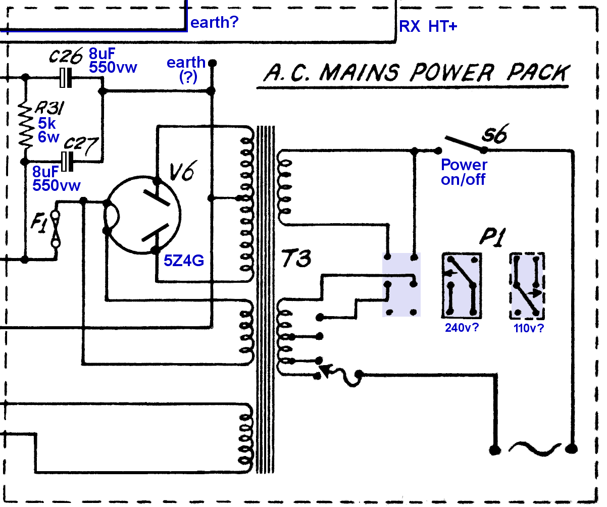
The transceiver could be powered from an AC mains voltage of 100 - 250v, 40 - 60 Hz by selecting the correct tap on the mains transformer primary. A reversible plug P1 allowed range selection of 100 - 150v or 200 - 250v.
The 5Z4G recifier valve V6 provided the HT+ feeds for the transmitter and receiver though fuse F1 (value not specified: probably 100mA).
Filtering was provided for the transmitter HT by a single 8uF electrolytic, and for the lower receiver HT by an additional 5k resistor and 8uF electrolytic. The dropper resistor was rated at 6w, suggesting it was intended to carry a current of 20-30 mA. The user manual confirms that the receiver drew 25 mA at 250v. The transmitter drew 55 mA at 360v.
Heaters were fed from a single winding on the transformer. The total load was 2.3A at 6.3v, according to the user manual.
BATTERY POWER PACK
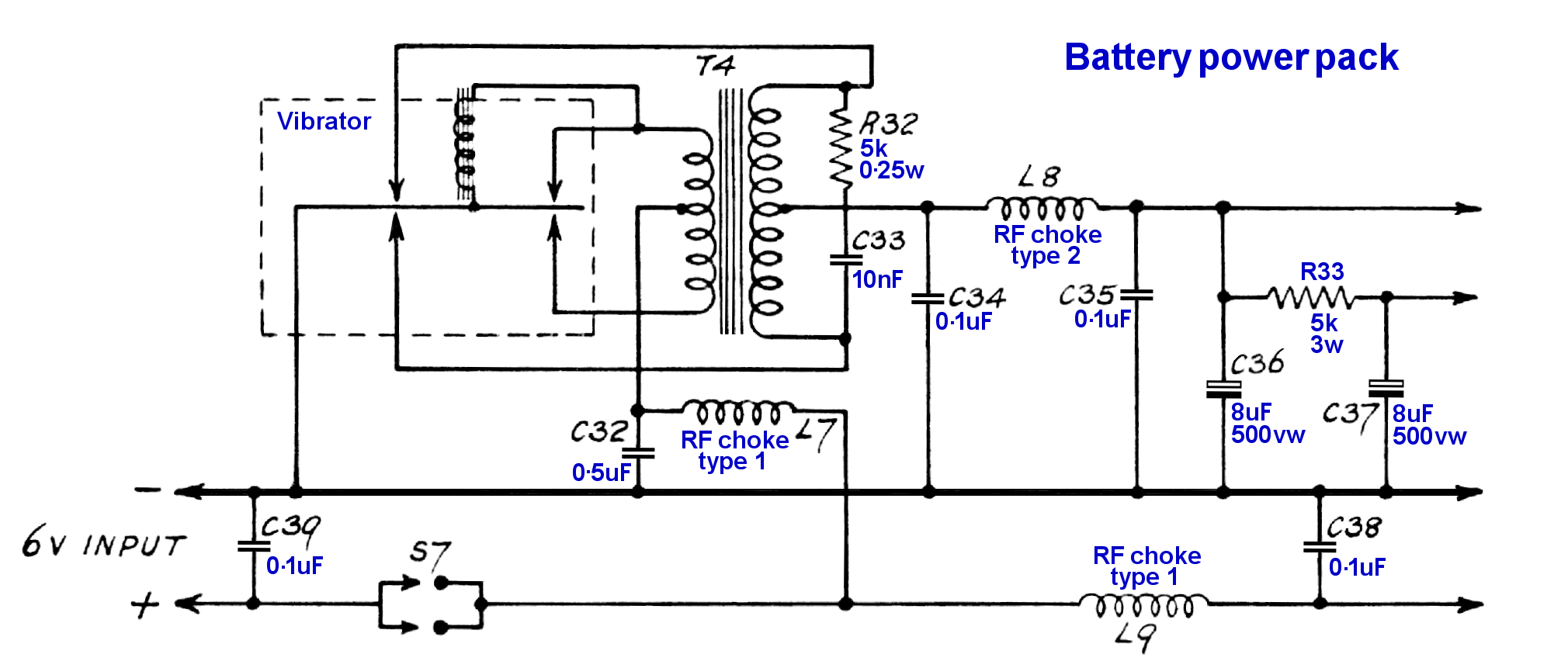
The system could alternatively be powered from a 6v battery, using a vibrator to generate HT.
The RF chokes are presumably sized to carry the currents required - around 3A for the type 1 and 100 mA for type 2.
The 3w rating for R33 seems too low - 25 mA receiver current would give a dissipation of 3.1w.
