
This article looks at how old wooden windmills, and particularly their sails, have come to be the shape they are. It tries to explain how the sails start rotating, why they don't self-destruct in a gale, and why a windmill sail looks like a piece of garden trellis. The design of sailing boats seems to be important, and also (to a lesser extent) basic aerodynamics.
Free energy?
Using the wind as a source of power seems such a simple and obvious idea that one might expect to find that there were windmills in England long before the Conquest. And yet there weren't any. Waterwheels have been around for much longer. The 6,000 mills recorded in the Domesday Book were most probably powered by waterwheels.
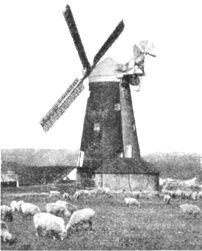
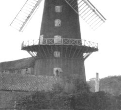
This rather grainy photograph shows a windmill on the Sussex Downs around a hundred years ago, when such sights must have been commonplace.
But it's a much more challenging task to extract energy from moving air than from moving water. The amount of water flowing through a waterwheel can be controlled quite closely by using artificial millponds and sluices, but the strength and direction of the wind can change dramatically during a day, or even in the course of a few minutes. 'The wind bloweth where it listeth', as St. John helpfully pointed out.
So the problem faced by an aspiring windmill designer is this: how can the energy in an erratically-moving mass of air be harnessed, and then used to drive a shaft at ground level which needs to rotate at a more-or-less constant speed?
European designers have pondered this problem for nearly a thousand years. The first English windmills seem to have been built in about the twelfth century, and since their introduction followed Richard Coeur-de-Lion's ill-fated attempt to retake Jerusalem in 1191, historians suppose that the Crusaders brought the technology back with them from the Middle East. Windmills seem to have been an Arab invention, along with algebra, the symbol for zero, and, apparently, mattresses. Yet once the first English mill had been built, it was quickly copied. Two hundred years later there may have been as many as 4,000 windmills in England. Cheaper to construct than watermills - because they didn't need a special water-course to drive them - they were still expensive capital investments, and they had to pay their way.
The first definite mention of an English windmill, as far as I know, was in the reign of Richard I. The head of the abbey at St. Edmondsbury (now known as Bury St. Edmunds) was at the time one Abbot Samson, a choleric and energetic cleric, whose chief weapon was widespread and indiscriminate excommunication of those who dared to oppose him. Carlyle, in Past and Present (1843), says that Samson,
... found all men more or less headstrong, irrational, prone to disorder; continually threatening to prove ungovernable.
... just like the managers of most engineering departments I've worked in.
One day, Abbot Samson discovered that an unauthorised windmill had been erected on lands under his control. The story of how he dealt with this threat to his income sheds an interesting light on life at the time. Carlyle tells it like this.
We said withal there was a terrible flash of anger in him: witness his address to old Herbert the Dean, who in a too thrifty manner has erected a wind-mill for himself on his glebe-lands at Haberdon. On the morrow, after mass, our Lord Abbot orders the Cellerarius to send off his carpenters to demolish the said structure brevi manu, and lay up the wood in safe keeping. Old Dean Herbert, hearing what was toward, comes tottering along hither, to plead humbly for himself and his mill. The Abbot answers:
"I am obliged to thee as if thou hadst cut off both my feet! By God's face, per os Dei, I will not eat bread till that fabric be torn in pieces. Thou art an old man, and shouldst have known that neither the King nor his Justiciary dare change aught within the Liberties without consent of Abbot and Convent: and thou hast presumed on such a thing? I tell thee, it will not be without damage to my mills; for the Townsfolk will go to thy mill, and grind their corn at their own good pleasure; nor can I hinder them, since they are free men. I will allow no new mills on such principle. Away, away; before thou gettest home again, thou wilt see what thy mill has grown to!"
The very reverend, the old Dean totters home again, in all haste; tears the mill in pieces by his own carpentarii, to save at least the timber; and Abbot Samson's workmen, coming up, find the ground already clear of it.
Holland
At the time windmills were used in England mainly for grinding corn, but the Dutch had a different and much more urgent need. Their country was being swallowed by the sea. To reclaim it, they needed power, and lots of it.
Before about 1400 Holland was a swamp, with just a few isolated settlements dotted here and there. Every few years the sea swept in and took over vast areas of the country. The great flood of 1421, for example, destroyed 72 villages and hamlets and drowned thousands. The people began to build defences against these attacks, damming the main channels and gradually converting into pools and lakes those areas that had formerly been connected to the open sea. Their next step was to reclaim the land by draining the lakes. To do this, the water had somehow to be lifted uphill to a place where it could flow safely back into the sea, so the engineers needed pumps and a power source to drive them.
They knew of two types of pump - the waterwheel, and the Archimedean screw, which looks rather like a giant corkscrew inside a tube. The revolving helix miraculously persuades the water to flow uphill. A similar design is apparently still used today in sewage plants.
Waterwheels were already being used to power corn mills in those few areas of the country that had suitable rivers, and using a waterwheel as a pump involves little more than arranging to drive the shaft instead of taking power from it.
And for a power source, there was always the horse.
 The mediaeval woodcut on the right illustrates a pump that seems to combine elements of both a waterwheel and an Archimedean screw. If you look closely, the plane of the wheel is not vertical. It is inclined at about 45 degrees, so that the water spilling out of the buckets falls outside the wall around the shaft. But I feel sorry for the chap in the pixie hat who walks endlessly round and round with the horse.
Where's the job satisfaction in that?
Horses may have been the first controllable power source, but the power a single horse can deliver - 746 watts, according to the textbooks - does rather limit what can be achieved. Just to heat a room would take the power of four horses harnessed together (plus a man in a pixie hat to look after them). Horse-power would have been a totally inadequate solution to the Dutch problem of draining large lakes. Projects with power demands in the tens of kilowatt range require something altogether more powerful.
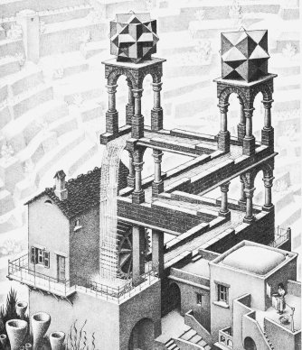
Free energy has long been the researchers' holy grail, of course. Nuclear fission, touted in the 1950s as producing electricity that would be too cheap to meter, turned out to have huge hidden costs. No doubt the first fusion reactor too, when it eventually gets built, will end up costing far more than its enthusiastic promoters expect. One of my favourite Escher drawings shows how easy it would be to get limitless power from a waterwheel if only the laws of perspective applied instead of the laws of physics.
But the Dutch engineers were pragmatic men, more interested in solving real problems than impossible dreams. They needed a reliable source that would provide them with lots of free energy. If they had lived in a mountainous country filled with streams rushing down steep slopes, no doubt they would have perfected the waterwheel. But as their homeland is flat and windswept, they worked with what they had.
It's still common to see a working windmill in Holland (I should really say, in the Netherlands - strictly speaking, Holland is just that region of the country nearest to the sea) but it's been over a hundred years since this was true of England. I wondered why this should be so. Like Holland, East Anglia has few hills and is exposed to the North Sea ('Very flet, Norfolk' as Noel Coward observed), yet unlike Holland the Norfolk windmills are now just tourist attractions. Impressive machines they are, too, but about as much use as chocolate teapots.
Flanders
There's a windmill museum at Villeneuve, just east of Lille, and worth a visit if you're interested in the technology. The main attraction is a (reconstructed) mill designed to extract linseed oil from flax seed and convert the residue to animal feed.
The process is quite complicated. First, the flax grains are put through a roller to break the husks, then hammers crush the seed to flour. Next, the flour is heated to release the oil, put into linen bags, and placed inside a hinged wooden press lined with horsehair. Hammers are arranged to fall onto wedges that crush the bags. As the flour is compressed, the oil drips out into a container below, and the contents of the linen bag become oil cake. (This could well have been what Marie Antoinette was talking about when she said dismissively of the starving peasants, "Oh, let them eat cake!")
The sail assembly is said to weigh 35 tons, and the sails are 26m long, tip to tip. They drive 7 hammers, via a camshaft, but light winds give enough energy to power just a couple of the hammers. The mill's beams are made of oak, and its walls of poplar; the teeth of the small wheels are made of applewood, and those of the brake wheel of "charme" (we can't find a translation of this word).
Why do the sails go round?
There's something beautiful about a well-designed machine, whether it be a steam locomotive or a fighter aircraft, a clock or a racing car. Every component, large and small, is there for a reason. Each has been made in a particular way, from the most appropriate material available, to interact with the other components in just the way their designer intended. Most important of all, a machine is useful. Someone has paid good money to have it built.
For me at least, part of the pleasure I get from machines comes from trying to understand how they work. Windmills are not just pleasing to look at. They are machines, and like all machines they have been engineered to do a useful job at minimum cost. Every single component has been thought about, and designed, and optimised.
At first glance, it seems obvious how windmills work. They have huge flat sails that face the wind, so when the sails are rotating they cut through the air just like the wings of an aircraft.
But then I asked myself, if the wind is blowing directly at the sails, why should they ever begin to rotate?
And whilst an aircraft's wing is a smooth solid surface, a windmill's sails seem to be mostly empty space. The wind would blow straight through the holes. That surely makes no sense.
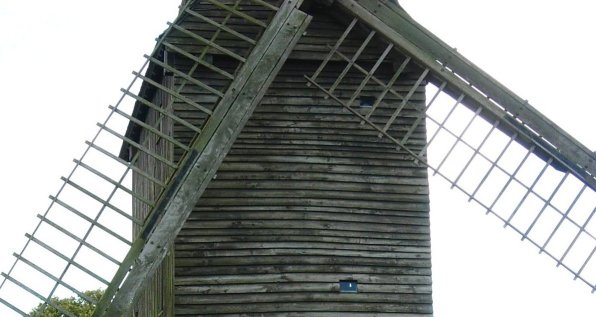
This one's sails seem to be all twisted, as though they had been left out in the rain. And why is there a sail on only one side of the stock (the spar attached to the hub)? Wouldn't the machine be better balanced with a sail on both sides? And why are the sails all set at different angles? What's the point of that? And why does this windmill have a bolt through its neck, like Frankenstein? And anyway, why do most windmills have four sails when modern wind turbines have only three?
I tried to find out the answers to these questions. My usual sources of information (my books, the internet, the local library, the county library) had practically nothing of any use. This was disappointing, but not really surprising - nobody builds windmills like this any more, so there's little point in writing books on how to do it. If I wanted to understand how windmills work I would have to sort it out for myself.
This was not a great surprise. Most of the engineering projects I've worked on have begun with questions. Engineers are paid to solve interesting technical puzzles by applying the laws of physics in new ways, to address new problems. If there's already a book on how to design something, the main problems have already been solved. Simply copying someone else's design - what I tend to dismiss as "cook-book engineering" - usually leads to a less than optimum solution, because each new situation offers a different mix of problems and opportunities. And anyway, I'd rather try to understand why something has been built the way it has rather than just shrug and say, oh well, they probably knew what they were doing. Experience has taught me that sometimes, they simply didn't.
So I decided to spend a little time thinking about the principles that guided these early millwrights, to see if I could understand why they built windmills in the way they did. The key question seems to be: How does the wind makes the sails revolve? Once I understood that, it should be easier to see why the sails have the shape they do.
Sailing a boat
Sailing ships capture wind energy and convert it into forward motion, so an obvious starting point in designing a windmill's sails would be to think about a sailing boat. Boats have been around for a very long time, and to be useful they must have some means of changing the direction of the force supplied by the wind into the direction the captain wishes to steer. With care, they can even sail into the wind.
The force of the wind acts on the sail, of course. That's what the sail is for. But the sail is attached to the boat, and it's the boat that moves. If it were a raft, it would move in whatever direction the wind was blowing, but a sailing boat is designed to go in just one direction - forwards. So from the perspective of someone on the boat, the force of the wind can be seen as having two related components - a wanted force pushing the boat forwards, and an unwanted force pushing it sideways. There's just one force, but to someone on the boat it's like the curate's egg - only good in parts. Engineers talk about resolving the force into its two components.
Windmills don't move, but they do need a force component that acts at an angle to the wind. Perhaps this second force could be used to push a windmills' sails round.
To make a shaft rotate, the sail must somehow twist the force of the wind through 90 degrees.
Suppose the sail and its mast are attached to a shaft, like this. The dashed lines show the plane through which the wind is blowing. The sail is deliberately set at an angle to this plane.
What will happen? Will the shaft rotate, or will it try to move along its own axis?
The answer is, it will do both. The force on the sail acts not in the direction of the wind but at right angles to the sail, as shown in the diagrams. If it didn't, sailing boats wouldn't work.
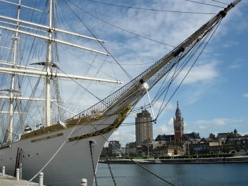
Many of the ropes visible in this picture are there to move the ships' sails to exactly the right compromise angle between the present direction of the wind and the ship's course. The others are mostly to keep the whole structure rigid and prevent it from collapsing under the forces applied to it. The ship experiences a rotational force too, but its keel stops it from being blown over.
There are only two ways the shaft can move (it's free to rotate, or to go backwards), so the designer need only worry about the forces acting in these two directions. The shaft experiences two separate forces - one pushing it backwards, along its axis, and the other (the turning force) at right angles to its axis. But this second force acts through the centre of the sail, which is at some distance from the shaft, and so its effect is to make the mast - and hence the shaft - rotate.
The size of the turning force evidently depends on the angle between the sail and the wind. The other force, pushing the shaft backwards, is not wanted and can be countered by building a structure that won't be blown over.
This is exactly the opposite approach to a sailing boat, which is designed to make maximum use of the force along its axis and to counter the sideways and rotational force by means of a keel.
Early windmill designs used simple canvas sails mounted on wooden frames, attached radially to a shaft which pointed directly into the wind. They worked - when the wind blew steadily, the shaft went round. But sudden gusts or abrupt changes in wind direction would make the sails flap uselessly, and the shaft might even begin to rotate in the wrong direction. Experiment showed that the system became more tolerant of wind surges if the leading half of the sail (the half that meets the wind first - the darker grey half in my diagrams) was simply removed, but the problem was only solved by making the sails more rigid. Heavier sails also increased the system's inertia, which made gusts less important.
What's the best angle for the sail?
The next question is, what should be the angle between the sail and the wind? The diagrams indicate that the turning force (the force that will do useful work) gets larger as the sail is rotated (anti-clockwise in this case) to make it more and more nearly parallel with the wind.
The logical conclusion of this is that windmills should be built with their sails edge-on to the wind, to use all the available turning force, with the wind flowing over the sails as it does over the wings of an aircraft. In fact, aircraft designers know this turning force as 'lift', and it's what makes aircraft fly. Windmill sails were actually called 'wings' in Anglesey (and 'sweeps' in Kent, and 'arms' in Yorkshire.)
But if the sails were mounted edge-on to the wind, when they went round they would flail wildly at the air like giant cricket bats, instead of slicing though it smoothly like swords. The resulting turbulence and air resistance would be enormous, and would seriously limit how fast the sails could rotate. This wouldn't do at all, since it was already known that the windmill's power output increases greatly as the speed of rotation rises.
On the other hand, if the sails were mounted square-on to the wind, there would be no turning force at all. So it's essential to set the sails at a compromise angle that will persuade them to start moving in slow-moving air, yet still give a reasonable power output in normal operation when the wind speed is higher. The optimum angle turned out to be about fifteen degrees, as shown in the diagram below.
As it happened, the first engineer to analyse this properly (in 1759) was one of my heroes - a Yorkshireman called John Smeaton. He pioneered the approach that engineering is an applied science and not just a collection of rules-of-thumb. His achievements included making waterwheels more efficient and building the first Eddystone lighthouse that didn't fall down. Scientists may live in ivory towers, but engineers design them.
There was one more oddity about the wind's behaviour that had to be tackled. When you stand on top of a tall building, the wind feel stronger than it does at ground level, and that's because it is stronger. As the wind blows along the ground, those layers nearest the earth lose energy through friction, and slow down. The result is that the wind appears to blow slightly downwards, towards the earth, and so the windmill sails work better if they rotate in a plane which is tilted slightly upwards (again, by about 15 degrees), as can be seen in the photographs of real mills a little later.
Coping with different wind speeds
Once the sails are capturing the wind energy efficiently, the next problem is how to transmit the power down to ground level, where it can be applied to the job in hand - driving a pump, or turning millstones, or whatever it might be.
Clearly, the need is for a fixed vertical shaft inside the mill which is driven from the shaft on which the sails are mounted. This is not quite as straightforward as it sounds, because for one thing the sails must always face into wind, no matter which direction the wind is blowing from, and for another the shaft on which the sails are mounted (known as the 'wind shaft') is not quite horizontal.
Since the wind shaft bearings are firmly attached to the mill frame, turning the sails into wind involves rotating the whole structure - the entire mill - about its vertical axis. Early mills were supported on a hollow post, with the drive shaft running down its centre. But by the 1600s it had been realised that only the cap need rotate, which meant that the body could be heavier, and taller, and more strongly built.The gearing mechanism would originally have been as simple as the one I show here, but was again soon refined into one based on hand-carved wooden bevel gears. Even though they would have been well-greased with animal fat, the wear rate of those gear teeth must have been a constant worry to the miller.
The only major design problem remaining to be solved is how to cope with gales. If the wind speed becomes excessively high, the sails will whirl round frantically until either something breaks or an overheated bearing catches fire.
To avoid disaster, the system needs to be fitted with some sort of brake, which can convert the excess rotational energy into heat. The solution universally chosen was a form of drum brake in which the shoe (made of wood) was made to rub against the outside of the large gearwheel (also made of wood) on the wind shaft. This wheel naturally came to be known as the brake wheel. It was a high-risk design - if the wind speed rose, and the miller didn't apply the brake in time, the braking system would not be able to cope, and the whole mill would be set ablaze.
Power output depends not only on the wind speed, but also on the area swept by the sails. Long sails generate more power than short ones, and a typical sail might be 10m. long and 2m. wide. If it were made of solid wood it would obviously be very heavy indeed, but experiment showed that it didn't need to be solid.
Lift and drag
Ideally, the sails should rotate at a constant speed whatever the wind conditions, and in practice this means that additional braking must be applied when the wind speed is high. The most elegant solution would be if the moving sail could itself somehow supply a braking force which increased with speed, and it turns out that this happens if the sail is constructed as an open lattice instead of with a smooth continuous surface. The holes generate turbulence, which acts as a brake (and also reduces lift). Aircraft designers call this braking force 'drag', and do their best to avoid it, which is why aircraft wings don't have big holes in them.
But whilst increased drag is an advantage when the sails are actually rotating, the reduced lift makes the system more difficult to start. The wind speed has to be higher before the sails can generate enough lift (turning force) to get them moving. So the mill needs solid sails when the wind speed is low, but open lattice sails when the wind is blowing more strongly. How can this dilemma be resolved?
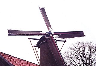
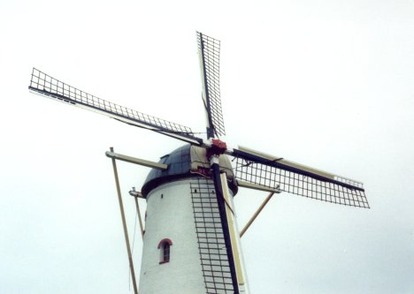
The answer is, by using open lattice sails, and covering them with cloth when the wind is light.This mill is in the middle of the small town of Zierikzee in the Netherlands. It was a cloudy and showery day with hardly any wind when we were there in 2005, but the mill was working. The photograph also illustrates that although the inner edges of the sails (near the hub) do meet the air at about 15 degrees, the angle at the tips of the sails is very much less. This gradual change in angle was another of Smeaton's ideas.
It arises from the fact that the speed at which the edge of the sail cuts through the air varies from zero at the hub to a maximum at the sail tip. In fact, when the mill is running at its full speed of 20 rpm, the tip of a 10m. sail is slicing through the air at about 21 metres/second (45 mph). Like all moving machinery, windmills can be dangerous. Being hit on the head by several tons of wood travelling at that speed could easily spoil your whole day.
The area of sail covered by cloth could be tailored to suit the wind conditions. If the wind speed picked up, the miller could shorten sail, just like the captain of a sailing ship. But that would involve stopping the mill and adjusting each sail in turn. He would save time and money if the sails could be designed to cope automatically with a wider range of wind speeds.
Leading-edge slot
This is a post-mill near Abbeville, in France. Like the mill at Zierikzee, the leading edge of each sail has been extended forwards, but the mill-wrights who did the work have deliberately left a small gap between the new leading edge and the main wing spar (the stock).
Why did they do that? What purpose does it serve? To find out, I had to find out a little more about how an aircraft wing actually works.
Why does a wing generate lift? The answer is a bit more complicated than one might expect, because two things are happening at the same time. First, air meeting the leading edge of the wing is deflected upwards or downwards. The air pushed upwards is accelerated, so it speeds up and becomes thinner - its pressure falls. The air below the wing is not disturbed as much. So there is a pressure difference between the upper and lower surfaces of the wing, and this tends to lift it upwards. However, at the trailing edge of the wing, the higher-pressure air tries to flow round into the lower-pressure region above the wing.
The higher-pressure air doesn't normally get very far. The angle at which the air meets the wing (A in the diagrams, because in aerodynamics A is known as the angle of attack) determines how far this unwanted higher-pressure air can flow up along the top surface of the wing. As this angle becomes larger, the invading higher-pressure air penetrates further and further. Its effect is to push the lift-generating low-pressure region higher above the wing surface, which means the air has to speed up even more, which means that the lift force actually increases as angle A becomes larger. But eventually the higher-pressure air creeps sufficiently far up the top surface that it detaches the low-pressure region altogether from contact with the wing. Airflow then becomes chaotic and turbulent, and lift falls abruptly to zero. A pilot would say that the wing has stalled.
Unfortunately, a windmill's sails meet the air at the highest angle when the sails are stationary. Once they begin to move, their forward speed reduces the effective angle, as the diagrams below illustrate, and so the sails continue to revolve. Starting is the big problem.
The unknown genius who made starting easier did so not by adding complexity but by taking part of the sail away. He made a long slot-shaped hole in the sail, just behind its leading edge. The idea may have grown out of his rough-and ready hands-on knowledge of aerodynamics, but my guess is that he just happened to notice one day that a broken sail that was damaged in this way seemed to work better.
 When a slot exists just behind the leading edge, air from beneath the wing can flow through the slot and down along the top surface. This stops the air that is creeping upwards from below the wing from interfering with the low-pressure region (because now much of the lift is coming from the small section of wing ahead of the slot), and so the wing continues to generate lift even when the angle A is large.
High lift at a large angle of attack is exactly what is needed to make the sails begin to rotate.
The aircraft designer Fred Handley Page re-invented the idea in 1920. He used slotted wings to improve the low-speed handling characteristics of his aeroplanes, and today all modern high-performance combat aircraft use slots to delay the onset of a stall. Maybe Sir Fred got the idea from looking at a windmill.
The slot can clearly be seen on the sails of this mill on the left, too. It's at Hessle, in Yorkshire, and was used for crushing limestone into the powder that formed the basis of many products from face-powder to fertiliser.
As a matter of fact, a distant cousin of mine used to own it. He began as a labourer in the chalk quarries, and by hard work, entrepreneurial skill (and probably a certain amount of luck), he ended his days as a rich man owning ships and other businesses, as well as this mill. It's an interesting story, and in due course it will appear in the Family History section of this website.
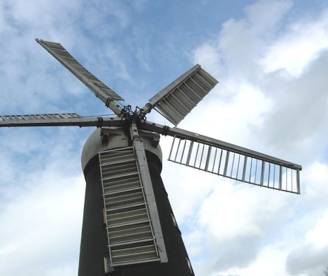
Curiously, the mill at Hessle seems to have been equipped with five sails instead of the usual four. Perhaps its location, on the north bank of the Humber, did not have the steady breeze that would be needed by a business that had to operate all the year round.
There are other five-bladed windmills - this one at Alford, for example - but the relatively slight improvement in efficiency was not usually considered a good enough trade-off for the additional complexity of the design. After all, the miller isn't actually paying for the wind to blow.
Patent sails
The sails of the two five-bladed mills pictured above are evidently not of simple lattice construction. Instead, they look more like a stack of open letterboxes. This mill seems to be fitted with the so-called 'patent sails', which were invented in 1807. They consist of a series of hinged shutters linked together, as shown in the drawing. By sliding the bar, the miller could control exactly how much lift and drag each sail generated, and hence optimise his mill's performance in winds of any speed.
But with five sails, the miller would have to take care to set the shutter positions identically on each sail. If one sail produced more torque than the rest, the out-of-balance forces would make the whole mill shake like a terrier with a rat. The inventor cunningly got round this by including a linkage from each sail through to inside the mill, which allowed the miller to adjust all the sails simultaneously.
Patent sails are naturally more complex and expensive to construct and maintain than ordinary sails, so a common nineteenth-century compromise was to build mills with two patent sails located opposite each other and two ordinary sails.
 It's not a coincidence that most mills were built with four sails. In an emergency - for example, when one sail has become damaged, but the mill needs to operate despite this - it was possible to run with just a single pair of sails. This option does not exist on a five-bladed windmill, and suggests to me that the designer of the Hessle mill may have been more interested in how impressive it looked rather than how well it worked.
It is clear from the photograph that the Hessle mill sails were stationary at the time it was taken, and the shutters have been left open in case a sudden breeze springs up. Perhaps it was a Sunday.
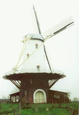
To turn the sails into the wind, the miller steers his mill by turning the cap - the structure on top of the building, to which the sails are attached - by means of the poles sticking out of it. They extend to a platform lower down, where they can be anchored to make the mill face in the most suitable direction.
This picture of the mill at Veere (a beautiful village on the Dutch coast) shows the arrangement a little more clearly.The mills in these photographs and the mill at Hessle were built with a steering platform. This mill was not in use when we saw it and the sails were left uncovered to offer minimum wind resistance. Strong winds can cause difficulties even with steel structures today. Large modern cranes - the T-shaped ones found on building sites - are regularly turned every hour of the day and night to face into the wind. Anyway, so says my son-in-law Ed, who spent a wet weekend keeping a bored eye on one.
This investigation into windmills led into some quite unexpected areas, and has increased the respect I feel for the engineers who solved the many design problems and came up with a workable system that their clients could operate successfully.
Oh, by the way, the reason why there are still so many working windmills in Holland seems to be because we have more coalmines than they do. Or at least, we used to have.