
I couldn't have written this article without Telephony (Vol 1), Herbert & Proctor, (1932).
Central Battery Signalling (C.B.S.) System No.2
In the 1930s there were less than two million telephones in the UK. None of them had keypads, and only a lucky few subscribers had dials. For most people, making a call meant picking up the receiver and telling an operator who they wanted to speak to. The chances were that the operator - who was almost always female - was sitting at a switchboard like this one.

This C.B.S switchboard is equipped to handle 60 subscribers - though it could be expanded to cope with 240 - plus 20 outgoing and 10 incoming junctions. On the switchboard, each subscriber appears as a jack (which is connected to the subscriber's telephone) and an indicator (to show when the telephone is in use). I've coloured the drawing to help distinguish the different components. Real switchboards weren't as gaudy as this one.
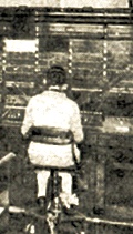
The switchboard was well over six feet tall, so either the operator spent much of her time standing up, or the equipment was designed to be operated by women with exceptionally long arms. The Librarian of Unseen University would have been ideal, as long as he was provided with an adequate supply of bananas and callers realised that "Ook?" meant "Number, please?"

A key component of the system was the "doll's-eye" indicator, which showed the operator whether or not a circuit was in use. The indicator is a sort of relay - when it was energised, a white disk appeared in the circular front window to attract the operator's attention.
Each subscriber had one, as did each incoming junction. (A junction was a circuit connecting to a neighbouring exchange. It was usually less than 15 miles long.)
The operator answered a call by plugging a cord into the caller's jack, and pressing the 'Speak' key. To complete the call, she plugged the other end of the cord into the called party's jack, pressed 'Ring', and when the conversation began, withdrew from the call and dealt with the next one. At the end of the call, the doll's-eye indicators warned her that the circuit was now idle, and she pulled out both plugs. This switchboard position was equipped with 14 cord circuits, so no more than 14 calls could be in progress at any one time. A fifteenth caller would simply have to wait patiently until a cord circuit became free.
This sketch of a similar (but smaller, and earlier, C.B.S.1) switchboard should make the principles a bit clearer, I hope. The cords are weighted, so that they automatically return to their storage positions.
The handle on the side is the Ring generator. The thinking was, why go to the expense of installing a separate ringing generator for a small exchange when the operator can just wind a little handle. She's only got a couple of dozen subscribers to look after, so it's not like she's not going to be overloaded with work.
In the circuit diagrams below, I've kept to the original drawing style as much as possible, with jagged resistors and curves instead of corners. I particularly like the capacitors.
The progress of a LOCAL call
The call begins when the subscriber goes off-hook. This causes current to flow from the battery, via the mA meter (as a rather crude check for line faults) and the indicator, down the line to the telephone, though the receiver and coil, and back to earth at the exchange though the indicator. The doll's-eye indicator drops to show that something has happened.

The operator answers the call by plugging a free cord circuit into the caller's jack.
A cord circuit looks complicated at first sight, but really it's just a transmission bridge (the transformer and 4μF capacitors) with a means of feeding current to the telephones on either side (via inductors LA, IA, LC, IC) plus a couple of supervisory indicators to keep the operator informed about what's going on.

Pushing a plug into the caller's jack automatically disconnects that indicator. Relay SA now operates (via the 1500Ω resistor tying the bush of the caller's jack to earth) and energises the cord circuit supervisory instead. But relay J does NOT operate, because the 1500Ω resistor prevents it getting quite enough current.
Current is fed to the caller's telephone via J2, IA and LA. Relay LA operates, releasing the supervisory. The operator now presses her Speak key and can talk to the caller. "Number, please?"

Operators in the 1920s seem to have had huge dreamy eyes and little tiny noses. Still, the callers couldn't see them, so it probably didn't matter.
The operator's telephone circuit made some attempt to limit the amount of sidetone she had to put up with by placing her earpiece in a bridge circuit. But since one of the bridge arms was the far-from-predictable line impedance, the sidetone level must sometimes have been uncomfortably loud.
Pushing a plug into the called party's jack causes the calling supervisory to operate, with current supplied via LC1. The operator now presses her Ring key, which applies ringing to the called party's line and operates the distant bell. Ring, ring.
She restores the Ring key to normal, and waits. The called party answers. "Hello?" Loop current now flows to the called subscriber, and so relay LC operates, disconnecting the calling supervisory via LC1. The operator's job is done, for the moment, and the subscribers can talk to each other.
Eventually, the subscribers replace their receivers and break the loops. Relays LA and LC release, and each operates a supervisory indicator. The operator sees this and unplugs both ends of the cord, ready for the next call.
The progress of a JUNCTION call

An incoming junction call operates an indicator. The operator sees it and plugs into the junction jack. This action disconnects the indicator, but relay SA operates and SA1 operates the supervisory. This time, relay J has enough current to operate, because junction jack bushes are earthed directly. Then J1 disconnects SA and keeps the supervisory operated, whilst J2 disconnects the battery connected to the incoming junction A-wire (via IA and the plug ring).
The operator presses her Speak key, restoring battery to the A-wire (which signals to distant operator that she is connected) and finds out what's happening. Releasing the Speak key removes the battery signal from the junction.
The operator then plugs into the called subscriber's jack, and presses her Ring key. When the called subscriber answers (with the Ring key now normal) relay LC operates, and LC1 connects battery to the junction A-wire again, giving a supervisory signal to the distant operator. Relay LA operates via battery on the B-wire coming from the distant exchange. LA1 disconnects the answering supervisory.
When the called subscriber hangs up, relay LC releases. LC1 removes the battery from the A-wire. This gives a clearing signal to the distant operator, who releases the junction. Relay LA releases, and LA1 operates the answering supervisory. (The calling supervisory was operated by LC1.)
The operator clears the call by unplugging the cord, and goes back to day-dreaming about the handsome young technician who keeps coming round to dust the relays ...