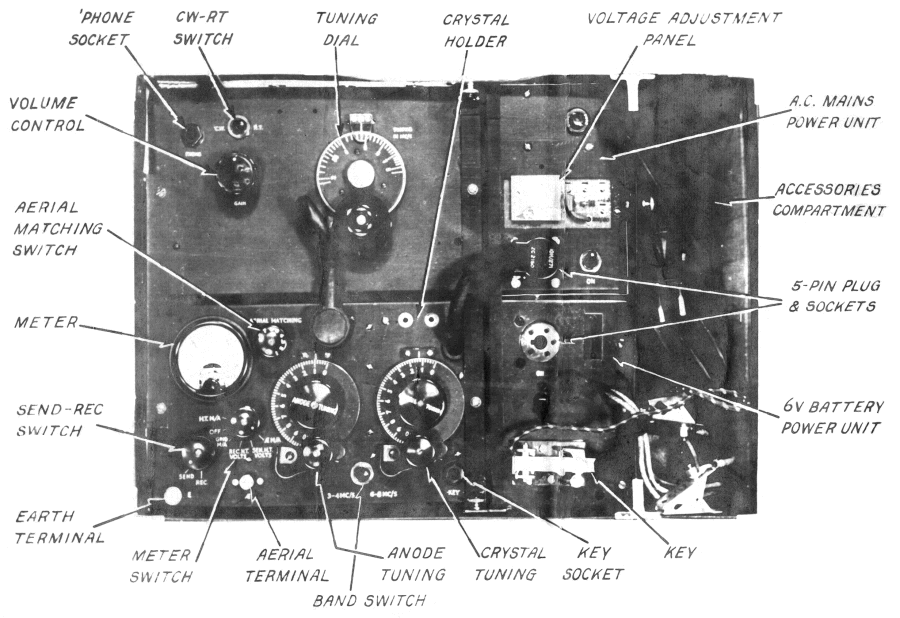
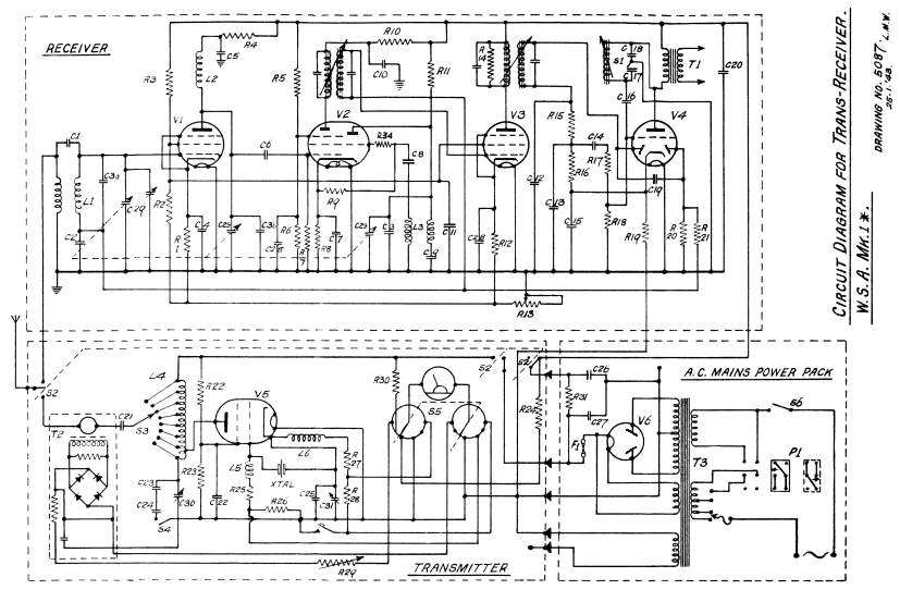
The Wireless Set A was developed by SOE in 1942 for use by British agents operating in wartime Europe. It was fitted into a suitcase. This user manual includes a circuit diagram and full instructions for setting up the aerial and tuning the transmitter.
The user manual for this suitcase radio turned up in my files.
I include it here to illustrate what cutting-edge radio technology looked like in the 1940s.
Click here to see complete circuit diagrams

PORTABLE WIRELESS SET A Mk.1* USER MANUAL
Set Serial No . . . . . . . . . . . . . .
CONTENTS LIST
Case containing:-
- 1 Transmitter
- 1 Receiver
- 1 A.C. Power pack suitable for use on 100-150v. or 200-250v; 40-100 c.p.s.
- 1 6 volt Battery Power Pack
- 1 60 ft. Aerial wire
- 1 10 ft. Earth Wire
- 1 Transmitting Key
- 1 Pair of headphones (low impedance)
- 2 Brass Pins to convert mains plug to Continental fitting
- 2 Crystals (between 3 and 4 Mc/s)
- . . . 1.
- . . . 2.
The following spares are provided:
- 12 Fuses
- 6 Bulbs
- 1 Transmitting valve type ATS25 (807) (V5)
- 2 Receiving valves type ARP34 (EF39) (V1 & V3)
- 1 Receiving valve type ARTH2 (ECH35) (V2)
- 1 Receiving valve type AR21 (EBC33) (V4)
- 1 Rectifying valve type 5Z4G (AU13) (V6)
- 1 Vibrator (synchronous type)
N.B. For battery operation a 6 volt car type accumulator must be obtained. This is not supplied.
OPERATING INSTRUCTIONS
Aerials
60 ft. of aerial wire is provided and it is desirable that as much of this as possible should be used, and in any case 25 feet must be regarded as the absolute minimum. It is also important to arrange the wire as high as possible, while keeping it away from earthed objects. In general, outdoor aerials will be better than the indoor variety, while of the latter, one erected in an upper room or loft is preferable to one on the ground floor. Plug one end into the insulated socket, marked AE, mounted on the transmitter.
Earth
A good electrical connection must be made to an to an existing earth tube, a main water pipe or central heating system. If these are not available, a wire of the same length as the aerial should be suspended underneath it, preferably two or three feet above the ground. The earth wire should be connected to the terminal on the transmitter marked E.
A.C. Power Pack
100-150V, 200-250V; 40-100 c/s. Valve 5Z4G.
Ascertain whether the mains are A.C. or D.C. The mains power pack must be used on A.C. mains only. Ascertain the voltage by reference to electrical apparatus in use, the electric light meter or the markings on electric light bulbs.
Adjustment of the Mains Power Pack to suit the supply voltage:
The waterproof strip on the power pack is unfastened, disclosing a five-pin plug with an arrow which indicates the range for which the plug is set and a flexible lead with a screw connector for the exact voltage. For example, for operation on 220 mains the arrow on the plug would point to 200-250, and the lead would be fixed by the screw to the socket marked
- 215 -- 235
- --------------
- 115 --135
The waterproof cover must be refastened before the mains connection is made.
The power for the transmitter and receiver is fed from the power pack through a five-pin socket on a short cable from the power pack and a five-pin plug on the cable connected to the transmitter.
When the aerial and earth have been fixed up and the A.C. mains unit adjusted as described above, withdraw the mains lead from the suitcase and adjust the plug to suit any available socket or lamp-holder, but do not switch on. Plug the key and telephones into the sockets on the transmitter and receiver respectively.
If the supply voltage cannot be discovered, adjust the power pack, as described above, for 250 volt operation. Set the SEND. REC. switch to SEND and the meter switch to SEN. H.T. VOLTS. Plug the mains connector in and switch on. The meter reading should now be approximately 475 volts. If it is less than 450 volts, the mains adjustment should next be set on the 215-235 volt tap, and the H.T. volts again read. This must be repeated on progressively lower settings if necessary, until the H.T. voltage reading lies between 450 and 500 volts. Switch off the current and do not finally connect up the power supply until ready to operate.
With an internal dissipation of 40w and no ventilation, I suspect the suitcase would have warmed up nicely.
The consumption is 60 watts when transmitting and 40 watts when receiving.
Battery Power Pack
For battery operation a large capacity 6 volt accumulator is required. This is used to drive the battery power pack which will then supply the set when mains are not available. The current drain is 7 amperes when transmitting and 4½ amperes when receiving.
To change to battery operation:
(a) Switch off the A.C. power supply.
(b) Remove the 5-pin plug from the A.C. power pack and insert it in the 5-pin socket on the battery pack.
(c) Connect the spring battery clips to the accumulator terminals: red clip to positive (+) terminal and black to negative (-) terminal.
(d) Put the switch on the battery pack to "on". A faint hum will be heard from the pack if everything is correct.
NOTE. If the battery pack is set up like this before operating on the A.C. power pack, it will be possible to change over in a few seconds should the need arise.
The original circuit was apparently designed by SOE's Station IX in 1942 (according to "SOE - the scientific secrets", Boyce and Everett, Sutton 2003).
The circuit diagram I have is however dated "25.1.43", so the Mark 1* was evidently a revised design, and capable of 8 watts output as against the original 5 watts.

[The circuit diagram really does show a direct short-circuit across the aerial current detector bridge. I assume this is probably a mistake, though I doubt the diodes available in 1942 would have performed well at these frequencies. Maybe the circuit worked better like this.]
Click here to see complete circuit diagrams and a brief discussion of the circuits
I've written about valves here. There is an explanation of how they work, and photographs of some valves with and without their glass envelopes.
RECEIVER
- Valves: ARP34, ARTH2
- Frequency coverage: 3-8 Mc/s
- Intermediate frequency: 470 Kc/s
- Power supply: 250V, 25 mA; 6.3V, 1.2A
Tuning Procedure
(a) Turn the knob marked SEND-REC. on the transmitter to REC. and switch on the current. After a few seconds a faint hum will be heard in the telephones.
(b) Set the CW-RT switch to suit the type of signal to be received
(c) Set the TUNING dial to the frequency it is desired to receive, and adjust the volume control until signal strength is comfortable.
TRANSMITTER
- Valve: ATS25
- Frequency coverage: 3-4 Mc/s, 6-8 Mc/s.
- Power output: 8 watts.
- Power supply 360V, 55mA; 6.3V, 1.1A.
Tuning Procedure
(a) Select a crystal of the desired frequency, or half the desired frequency should it lie between 6 and 8 Mc/s., and plug it in. (N.B. Operation in the range 6-8 Mc/s. is only possible by doubling.)
(b) Set the band-switch marked "3-4 Mc/s" - "6-8 Mc/s." to the position indicating the band in which the desired frequency lies.
(c) Set the CRYSTAL TUNING scale to 5.
(d) Set the AERIAL MATCHING switch to position 8.
(e) Turn the SEND-REC. switch to SEND.
(f) Set the meter switch to GRID M/A and depress the key, when the meter should give a small reading. This shows that the valve is oscillating.
(g) Turn the meter switch to AE M/A and keep the key depressed while making the following adjustments. (The key should, however, be released while the AERIAL MATCHING switch is being moved.)
(h) Set the ANODE TUNING control for a maximum reading on the meter.
(j) The AERIAL MATCHING switch is now moved progressively step by step, while adjusting the ANODE TUNING control to give a maximum readiing at each step, until the position is reached beyond which no further increase in meter reading can be obtained.
(k) The CRYSTAL TUNING control is now adjusted for maximum meter reading. (The setting will, in general, be found to be nearly correct at this stage if the previous adjustments have been carried out correctly. Large adjustments should only be necessary when using crystals with frequencies lying close to 3 Mc/s or 4 Mc/s.)
(l) The key is now released and transmission may commence.
ALTERNATIVE METHOD
With certain combinations of frequency and aerial it may befound that the method of tuning detailed above in sections (g),(h) and (k) gives meter readings which are inconveniently small. The following procedure should then be adopted:
(m) Set the meter switch to M/A (the meter now reads anode current) and keep the key depressed while making the following adjustments.
(n) Rotate the ANODE TUNING control until the meter reading "dips" to a minimum.
(o) The AERIAL MATCHING switch is now moved progressively step by step. At each step the ANODE TUNING control is adjusted to give a minimum reading on the meter until a setting of the switch is found at which the value of this minimum is as large as possible.
(p) Leaving the ANODE TUNING and AERIAL MATCHING switch set, adjust CRYSTAL TUNING for a maximum meter reading.
(q) The key is now released and transmission commenced.
NOTE
(i) The transmitter H.T. voltage, measured by the meter when the switch is in the SEN.H.T. position and with the key up, is proportional to the input voltage. The readings can therefore be used as an indication of the state of the battery when an accumulator is being used as the source of power. The grid current (GRID M/A) gives a measure of crystal current.
(ii) It is advisable to switch to receive at all times when not actually transmitting, and in particular not to keep the key depressed any longer than can be avoided.
APPENDIX A: AERIALS
The people operating this equipment would not have had much training or experience in setting up radio transmitters, and it's interesting that it was felt necessary to include a section on aerials.
As someone once remarked, "All aerials work, but some work much better than others."
The most usual type of aerial is the so called Marconi aerial which consists of a length of wire, one end insulated and the other end attached to the aerial terminal of the transmitter. A second length of wire joins the earth terminal of the transmitter to a conductor entering the ground. In this type of aerial the main losses are due to the resistance of the earth connection and every effort must be made to obtain as good an earth connection as possible.
The rated power of a transmitter is the power it will deliver to a suitable aerial but the power delivered to the aerial is not the power radiated by the aerial, which is always less and unless the aerial-earth system is efficient may be very considerably less. The remainder of the power is dissipated as heat in neighbouring objects such as walls, etc., and in the ground.
CURRENT DISTRIBUTION IN AERIALS.
If a long wire, insulated at one end, has the other end attached to the aerial terminal of the transmitter, an alternating current is produced in the wire, the amplitude of which varies along the wire. For a long wire the current reaches a maximum at a distance of a ¼ wavelength along the wire and then decreases. See Fig. 1.

Since the power radiated is proportional to the square of the current, it is clearly desirable to have at least one current maximum occur somewhere along the aerial. The shortest aerial which can be considered reasonably efficient is a quarter-wave aerial.
| FREQUENCY | 3 Mc/S | 6 Mc/S | 12 Mc/S | 16 Mc/S |
| WAVE LENGTH | 100 metres | 50 metres | 5 metres | 20 metres |
| ¼ WAVE LENGTH | 25m | 12½m | 6¼m | 5m |
EARTH RESISTANCE
The resistance of the earth connection usually varies from about 10 ohms, obtained when the earth wire is soldered to a main water pipe near to the ground to about 100 ohms, obtained from a moderate earth connection.
| Earth Resistance in ohms. | 10 | 50 | 100 | |
| Radiated power as a percentage of the power in the aerial | 1/4 wave | 80% | 44% | 29% |
| 1/8 wave | 50% | 16% | 9% | |
| 1/16 wave | 20% | 5% | 2½% | |
The amount of power that can be afforded to be wasted when using suitcase sets is small, it is therefore never any use trying to use a shorter aerial than 1/8 wave and this only in conjunction with a very good earth.
ERECTING AN AERIAL
It is not usually practical to erect a vertical ¼ wave aerial although this would be very efficient, but at least this length of wire and more if possible should be erected with a long vertical or rising portion and the top bent in one way towards the horizontal as in an inverted L. The exact length of wire is not critical as the transmitter is matched to the aerial in use during the tuning operations.

The whole should be left well away from earthed objects such as buildings, cliff sides, surrounding trees etc., and the end not attached to the transmitter should be insulated. In dry weather the rubber covering of the wire will be sufficient insulation but in wet weather it would be better to use an insulator. An old bottle neck may be used for this purpose.
This part of the document has been damaged at some time in the last 75 years, and the words in square brackets [] represent my best guesses of what the writer intended.
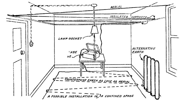
For me, this drawing shows more clearly than any spy novel just what it must have been like.
[A good earth] is most important. The ideal would be to solder a short length of wire to a [copper pipe] buried in moist earth near to the transmitter and to attach the free end of the [wire to the Earth] terminal of the transmitter. Failing this a copper earth tube, a large coil of barbed [wire that has been] well scraped, or some such metal receptical could be buried instead, but it is most [important that the object] attached to the earthwire should be clean metal, a good electrical con[nection] should be made and that the ground should be moist.
[Using] a water pipe may be convenient. Choose a cold water pipe near to the ground if [possible, rather] than a hot pipe which may be loosely attached to dry walls in several places before [making] a good earth connection. Scrape the pipe clean before attaching the earth wire.

[When no water] pipes are available a length of wire arranged in zig-zag fashion or a piece of wire netting [may] be placed underneath the floor covering and attached to the transmitter by a short earth wire. An efficient counterpoise earth may be made by arranging a wire of about the same length as the aerial wire, and insulated from earthed objects underneath the aerial wire and 2 or 3 feet above the ground. If indoors the counterpoise earth should be on the floor - perhaps under the carpet and well separated from the indoor aerial wire.
